- About us
- Product
- Dual-Junction Circulator
-

Dual-junction Microstrip Circulator
-

Dual-junction Drop-in Circulator
-

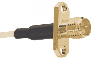
Dual-junction Coaxial Circulator
- Customized
- Technical Note
- News
- Contact us
Dual-junction Microstrip Circulator
Dual-junction Drop-in Circulator
Dual-junction Coaxial Circulator
Updated on:
Keywords: Miniaturized RF isolator, compact RF circulator, SMT microstrip circulator, miniaturized RF components, broadband circulator, X band, Ku band
As RF and microwave systems become smaller, lighter, and more integrated, engineers are under pressure to fit complete transceiver chains into mini circuits – dense PCB layouts with very limited space. In this environment, miniature RF isolators and circulators are no longer optional; they are essential to protect power amplifiers, stabilize oscillators, and enable reliable T/R switching.
In traditional RF systems, designers often had the luxury of using larger coaxial circulators or isolators with generous mechanical envelopes. Today, that approach rarely works. Radar front ends, SatCom user terminals, 5G/6G radio units, and compact T/R modules must all fit into smaller enclosures and thinner PCBs, while supporting higher data rates and broader bandwidths.
Miniature RF isolators and circulators solve several critical problems:
For OEMs and system integrators, the ability to source small-form-factor circulators and isolators directly influences the size, weight, and cost of the final microwave module.
Shrinking the form factor of a ferrite-based circulator or isolator is not simply a mechanical exercise. As the physical dimensions are reduced, the electromagnetic and thermal behaviours change significantly.
HzBeat focuses on RF circulators and isolators covering approximately 20 MHz to 200 GHz across microstrip, drop-in, coaxial, and waveguide platforms. Within this broad range, the microstrip and SMT families are specifically engineered for miniaturization and dense PCB integration.
The Surface Mount Technology (SMT) Microstrip Circulator series is designed for automated reflow assembly. Typical characteristics include:
For applications where footprint is critical but SMT reflow is not mandatory, HzBeat also offers miniaturized microstrip circulators. These devices retain the planar microstrip interface familiar to RF designers while reducing:
While circulators handle signal routing among three ports, many compact systems require two-port protection only. In those cases, SMT microstrip isolators provide one-way signal flow between source and load, using similar miniaturized construction and SMT-friendly packaging.
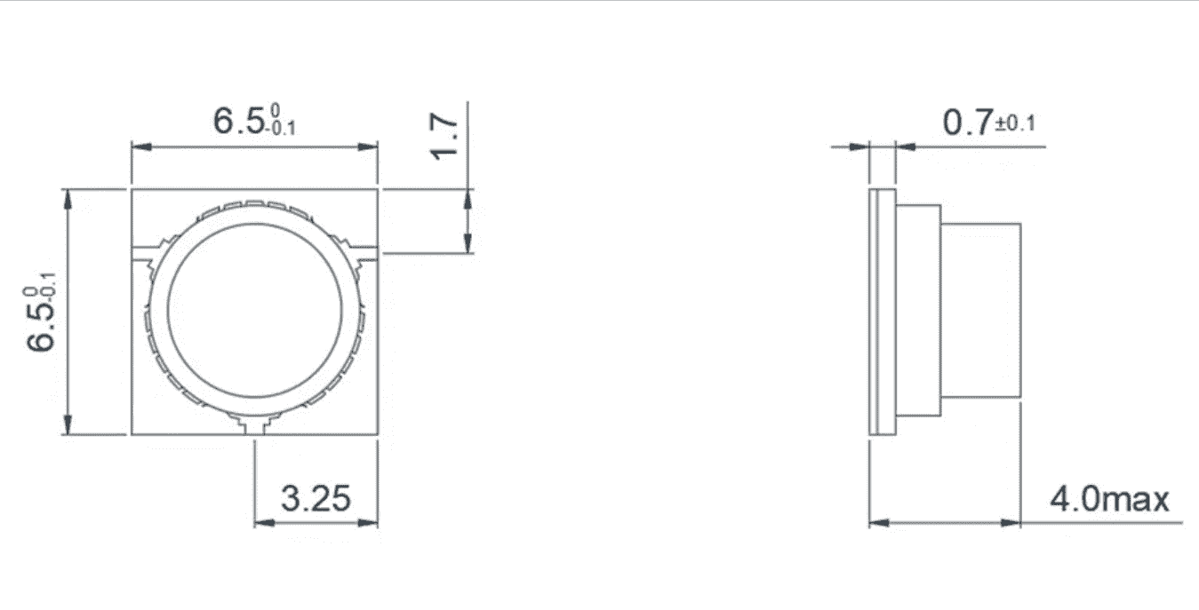
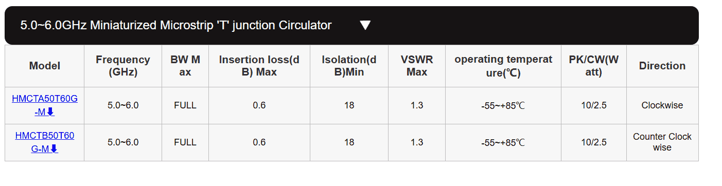
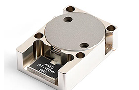
A concrete example of HzBeat’s miniaturization capability is the 5.0–6.0 GHz Miniaturized Microstrip “T” Junction Circulator family. Typical models, such as HMCTA50T60G-M and HMCTB50T60G-M, are engineered specifically for compact C-band front ends that must balance size, power, and robustness.
Mechanically, the device fits into an extremely small body:
The RF performance of this family highlights why miniaturized ferrite technology is so attractive:
| Model | Frequency (GHz) | Bandwidth | Insertion Loss Max (dB) | Isolation Min (dB) | VSWR Max | Operating Temperature (°C) | PK / CW Power (W) | Rotation Direction |
|---|---|---|---|---|---|---|---|---|
| HMCTA50T60G-M | 5.0–6.0 | Full band | 0.6 | 18 | 1.3 | −55 to +85 | 10 / 2.5 | Clockwise |
| HMCTB50T60G-M | 5.0–6.0 | Full band | 0.6 | 18 | 1.3 | −55 to +85 | 10 / 2.5 | Counter-clockwise |
Next-generation systems rarely operate in narrow single-carrier channels. Wide instantaneous bandwidths, frequency-hopping schemes, and multi-band architectures are now common. HzBeat’s microstrip and SMT families are designed to support:
| Feature | Conventional Designs | Miniature / SMT Microstrip Designs |
|---|---|---|
| Mechanical size | Larger housings, higher profile | Ultra-compact, low-profile, PCB-friendly |
| Integration | Often cabled or connectorized | Direct SMT or microstrip connection, minimal RF transition length |
| Assembly | Manual mounting, separate screws and fixtures | Reflow soldering in automated production lines |
| Typical use | Bench equipment, larger modules | Phased arrays, miniaturized front-ends, UAV radar, small SatCom terminals |
| Cost at scale | Higher assembly cost per unit | Optimized for high-volume SMT manufacturing |
Miniature RF isolators and circulators from HzBeat are well-suited to a wide range of compact microwave platforms, including:

Engineers designing compact RF front-ends can explore the following HzBeat product categories for detailed specifications and model selection:
“Miniature” refers to the overall mechanical footprint and height of the device, often realized through planar microstrip structures and SMT-ready packages. In many cases, the device measures only a few millimeters on each side, optimized for dense PCB layouts.
Not necessarily. With optimized ferrite materials, magnetic circuits, and careful PCB transition design, miniature circulators and isolators can maintain low insertion loss while still saving space. Designers should evaluate data sheets and performance curves rather than assuming that smaller always means lossier.
SMT microstrip circulators are generally optimized for moderate power levels in communication and radar front ends. For very high CW or peak powers, designers may still choose larger drop-in or coaxial structures. HzBeat provides multiple form factors so that power handling and size can be balanced to each application.
Use an isolator when you simply need one-way protection between a source and a load (for example PA to antenna). Use a circulator when you need to route energy among three ports – for example, sharing an antenna between transmit and receive paths.
Yes. Frequency band, bandwidth, footprint, port orientation, and power handling can be tailored to match a specific mini-circuit architecture. Engineers can contact HzBeat with target specifications to discuss customized solutions.
As RF and microwave systems move toward higher frequencies and denser integration, miniature RF isolators and circulators are becoming central building blocks of compact transceiver architectures. Planar microstrip and SMT devices from HzBeat provide the combination of small form factor, broadband performance, and reliable isolation that modern mini circuits demand.
By choosing appropriately miniaturized parts early in the design cycle, engineers can reduce risk, preserve performance margins, and unlock new possibilities for radar, SatCom, wireless infrastructure, and emerging 6G-class systems.
Relateds

About the Author
HzBeat Editorial Content Team
Marketing Director, Chengdu Hertz Electronic Technology Co., Ltd. (Hzbeat)
Keith has over 18 years in the RF components industry, focusing on the intersection of technology, healthcare applications, and global market trends.
Donec ipsum massa ullam dolor nullam justo contact us
Our mission is to revolutionize the RF industry through relentless innovation and cutting-edge advancements.
Chengdu Hertz Electronic Technology Co., Ltd. © Copyright - 2010-2025: All Rights Reserved.
