- About us
- Product
- Dual-Junction Circulator
-

Dual-junction Microstrip Circulator
-

Dual-junction Drop-in Circulator
-

Dual-junction Coaxial Circulator
- Customized
- Technical Note
- News
- Contact us
Dual-junction Microstrip Circulator
Dual-junction Drop-in Circulator
Dual-junction Coaxial Circulator
Updated on:
Keywords: miniaturized microstrip circulator, compact rf isolator, 5G module, UAV,
Across modern RF hardware, the gravitational pull is toward smaller, lighter, denser. UAV datalinks, portable radios, and high‑density 5G/6G modules demand non‑reciprocal protection without sacrificing precious board area. Hzbeat’s miniaturized microstrip circulator family is engineered for exactly these constraints: compact footprints, stable isolation, and low insertion loss over 5–37 GHz in C/X/K/Ka bands.
Compared with typical microstrip circulators, the miniaturized series prioritizes SWaP (size, weight, and power) while preserving essential RF figures of merit. In many systems, even a few tenths of a dB in insertion loss can shift the link budget; likewise, a stable 15–20 dB isolation prevents oscillation and protects sensitive LNAs from back‑propagating energy. The result is a pragmatic balance: compact mechanicals that still meet the electrical envelope expected by telecom, aerospace, and instrumentation teams.
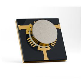
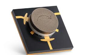
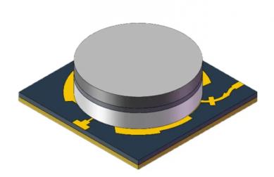
Miniaturized microstrip circulator — compact rendering (image source: hzbeat.com).
The rise of dense phased arrays, modular radios, and UAV payloads puts intense pressure on component geometry. Traditional waveguide or large drop‑in circulators may offer top‑tier power handling, but they rarely fit the volumetric budget of a compact module. Microstrip circulators, on the other hand, interface natively with 50 Ω planar lines, simplifying assembly and reducing parasitics.
Design intent: deliver robust non‑reciprocity in the smallest practical outline, with repeatable SMT‑like assembly and predictable RF behavior across temperature.
For integrators, this means fewer compromises: fewer transitions, shorter traces, tighter enclosures, and better thermal pathways. In practice, miniaturized units help stabilize power‑amplifier stages, isolate mixers, and protect receivers in duplex topologies where field conditions (mismatch, vibration, temperature swings) can otherwise introduce instability.
Hzbeat offers both T‑junction and Y‑junction realizations with clockwise (CW) or counter‑clockwise (CCW) rotation. T‑junction structures often target compact layouts and straightforward routing; Y‑junctions can provide useful bandwidth/port symmetry trade‑offs in certain bands. Practical device selection tends to hinge on the target frequency span, allowable insertion loss, and the mechanical envelope of the host board.
As a rule of thumb, tighter form factors require careful electromagnetic field shaping to maintain isolation and control return loss. Material choices and bias networks are tuned to limit drift over the −55 °C to +85 °C mission profile, while copper features and dielectrics are arranged to minimize discontinuities at the microstrip interface.
The miniaturized family spans key sub‑bands with representative performance envelopes shown below. Values are indicative; consult the live product page for model‑specific datasheets and tolerances.
| Band (GHz) | Topology | Max Insertion Loss (dB) | Min Isolation (dB) | Max VSWR | PK/CW Power (W) |
|---|---|---|---|---|---|
| 5.0–6.0 | T‑junction | 0.6 | 18 | 1.3 | 10 / 2.5 |
| 8.0–12.0 | T‑junction | 0.9 | 15 | 1.4 | 20 / 5 |
| 8.0–12.0 | Y‑junction | 0.9 | 15 | 1.4 | 20 / 5 |
| 15.0–17.0 | T‑junction | 0.5 | 20 | 1.2 | 20 / 5 |
| 33.0–37.0 | T / Y‑junction | 0.8 | 18 | 1.35 | 5 / 2 |
Power and loss increase with frequency due to physical line dimensions and dielectric/metal losses. Where thermal headroom is limited, consider heatsinking, metal‑in‑core boards, or short conductive paths to the chassis.
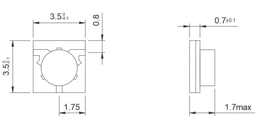
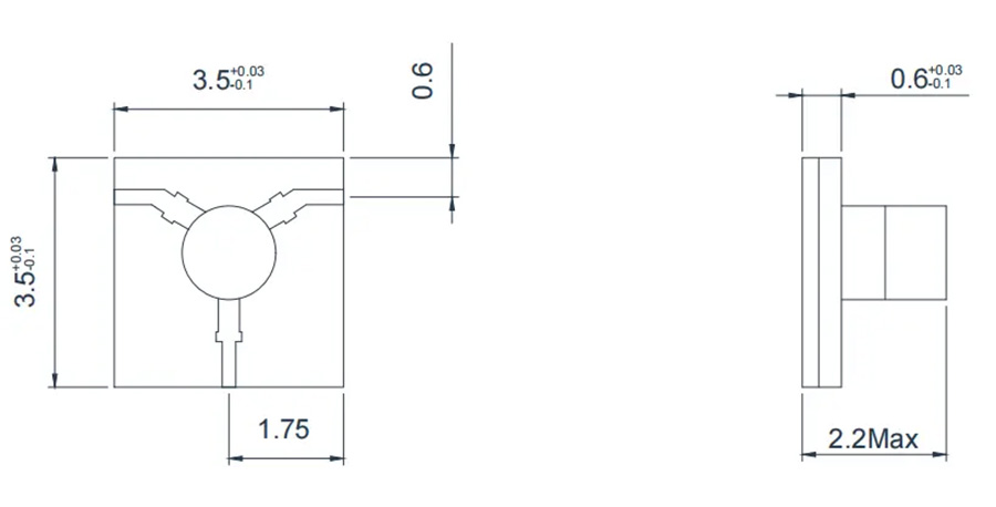
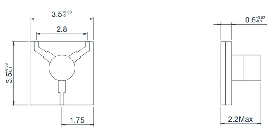
Mechanical discipline underpins RF repeatability. The outlines below (representative per band) illustrate how the miniaturized series fits common module footprints while preserving robust mounting and routing options.
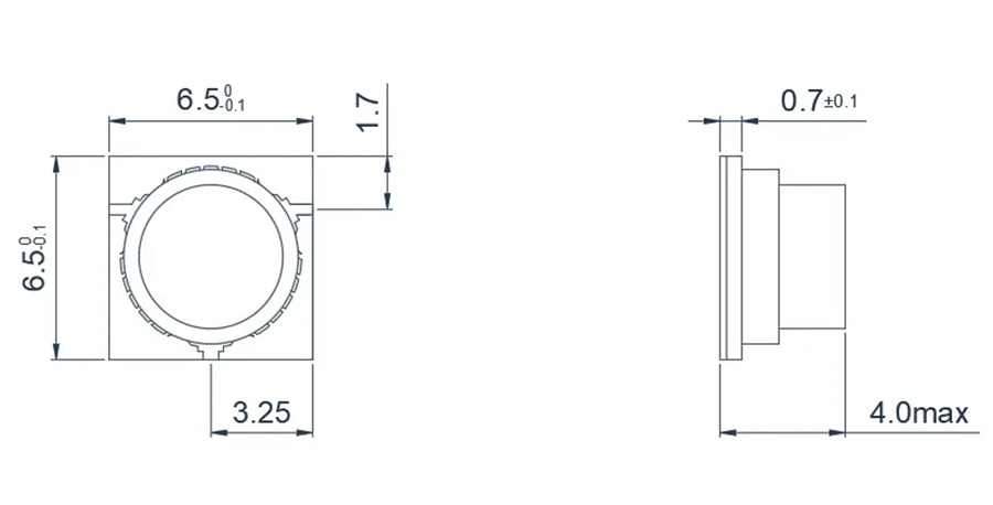
5.0–6.0 GHz T‑junction outline (typ.).
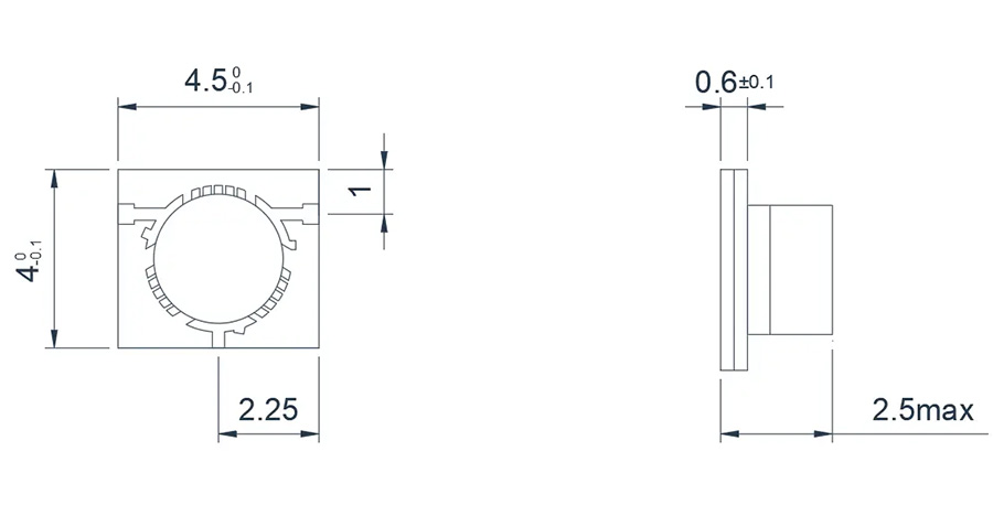
8.0–12.0 GHz T‑junction outline (typ.).
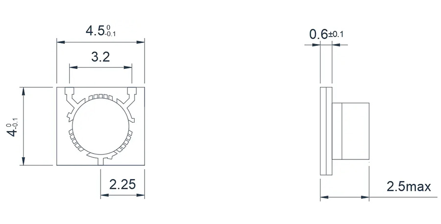
8.0–12.0 GHz Y‑junction outline (typ.).
15.0–17.0 GHz T‑junction outline (typ.).
33.0–37.0 GHz T‑junction outline (typ.).
33.0–37.0 GHz Y‑junction outline (typ.).
Payload‑limited UAV platforms benefit directly from miniaturized circulators: better link stability under dynamic VSWR, tighter packaging around PA/LNA chains, and controlled thermal paths to airframe or cold plates. When routing, avoid sharp bends at the microstrip interface; keep ground vias dense to prevent unintended mode conversion.
In handheld or body‑worn radios, mechanical shock and temperature swings are routine. Specify isolation and loss across the full temperature range and request S‑parameters over temperature where possible. For high‑density 5G/6G modules, co‑design with the enclosure team to reserve metal‑to‑metal contact points that shunt heat away from the ferrite core.
Compact ground terminals and on‑the‑move terminals often face size‑constrained RF decks. Miniaturized circulators simplify routing to phase shifters and PAs in active arrays. Ensure the target variant’s power margin aligns with expected crest factors and worst‑case mismatch in the field.
To streamline procurement, align early on the exact band, rotation (CW/CCW), and environmental envelope. When requesting quotes, include the intended operating temperature, expected VSWR at the antenna/load, and any vibration/shock requirements. For volume programs, Vendor‑Managed Inventory (VMI) can stabilize lead times.
Hzbeat provides model‑specific drawings, recommended land patterns, and (where applicable) environmental test data upon request. Always validate with the latest datasheet prior to design‑in.
The miniaturized series spans representative bands from about 5 GHz up to the mid‑30 GHz range, with specific models targeting C/X/K/Ka bands.
Both clockwise and counter‑clockwise variants are offered to match system routing.
Keep copper under the device well‑connected to ground; use short, thick thermal paths to chassis or heatsinks. Validate junction temperatures under worst‑case duty cycles.
Dimensions differ. Verify pad geometry, height profile, and any keep‑outs before substitution.
Relateds


About the Author
HzBeat Editorial Content Team
Sara is a Brand Specialist at Hzbeat, focusing on RF & microwave industry communications. She transforms complex technologies into accessible insights, helping global readers understand the value of circulators, isolators, and other key components.
Donec ipsum massa ullam dolor nullam justo contact us
Our mission is to revolutionize the RF industry through relentless innovation and cutting-edge advancements.
Chengdu Hertz Electronic Technology Co., Ltd. © Copyright - 2010-2025: All Rights Reserved.
