Manufacturing Process

Discover our precision manufacturing techniques and quality assurance processes

Microstrip components

Microstrip components

  • The circuit substrate and backplane are soldered. The solder is solder paste, or solder lug.
  • The bonding process is adopted between the circuit substrate, support medium, compensation sheet, and permanent magnet.
Waveguide components

Waveguide components

  • The cavity adopts duralumin conductive oxidation treatment.
  • The screw connection process is adopted between the cavities.
  • The bonding process is adopted between ferrite substrate, support medium, compensation sheet, permanent magnet and cavity
Drop-in/Coaxial components

Drop-in/Coaxial components

  • The Drop-in circuit is beryllium bronze plated with gold or copper and silver.
  • The resistance and cavity adopt welding process, the solder is solder paste, and the welding temperature is 205 °C.
  • The bonding process is adopted between the ferrite substrate, support medium, compensation sheet, permanent magnet and magnetic circuit.
  • The coating layer of the product shell is: industrial pure iron copper plating nickel plating.

Working Principle

Deep understanding of how our RF components work

Circulator Working Principle

Circulator

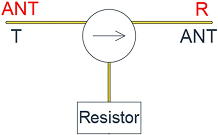
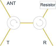
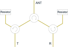
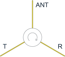
  • Circulators have three ports, and their working principle involves unidirectional signal transmission in the order of T→ANT→R.
  • Signals will travel according to the specified direction, with minimal loss when transmitting from T→ANT, but higher reverse loss when transmitting from ANT→T.
  • During signal reception, there is minimal loss when transmitting from ANT→R and higher reverse loss when transmitting from R→ANT.
  • The direction of the product can be customized for clockwise and counterclockwise operation.
  • Application: T/R components

Isolator

  • the working principle of an isolator is based on the circulator’s three-port structure with the addition of a resistor at one port, converting it into two ports.
  • When transmitting from T→ANT, there is minimal signal loss, while most of the signal returning from ANT is absorbed by the resistor, achieving the function of protecting the power amplifier.
  • Application: Single-transmit or single-receive components
Isolator Working Principle
Dual-Junction Circulator

Dual-Junction Circulator

  • The working principle of the Dual-Junction Circulator involves integrating a circulator and an isolator into one unit.
  • This design is an upgraded version of the circulator, and the signal path remains as T→ANT→R.
  • The purpose of this integration is to address the issue of signal reflection when the signal is received at R from ANT.
  • In the Dual-Junction Circulator, the signal reflected from R is directed back to the resistor for absorption, preventing the reflected signal from reaching the T port.

Triple-Junction Circulator

  • The working principle of the Triple-Junction Circulator is an extension of the Dual-Junction Circulator.
  • It integrates an isolator between T→ANT and adds a higher reverse loss and an additional resistor between R→T.
  • This design significantly reduces the likelihood of damaging the power amplifier.
  • The Triple-Junction Circulator can be customized based on specific frequency range, power, and size requirements
Triple-Junction Circulator

Failure Mode

Understanding common failure modes and root causes

Failure Mode Analysis

Root Cause Analysis

weld icon

Soldering Issues

  • Poor solderability of input and output terminals
firewall icon

Material Issues

  • Cracks in ferrite substrate
lightning icon

Resistor Issues

  • Open circuit in a resistor
bull's-eye icon

Other Issues

  • Other failures

Storage Conditions

Environmental requirements guide

thermometer icon

Temperature

15-25°C

water-drop icon

Humidity

25%-60%

fog icon

Atmosphere

No harmful gases

magnet icon

Magnetic Field

No strong magnetic field

ruler icon

Safe Distance

Devices above X-band

≥5 mm

X-band and C-band devices

≥10 mm

Devices below C-band

≥15 mm

Instructions for Use

Operation Guide

Microstrip Drop-in/Coaxial Waveguide SMT Cleaning
  • Microwave circuit in the form of microstrip transmission, microstrip structure, circulator with line structure and isolator can be selected.
  • When decoupling and matching between circuits, microstrip isolators can be selected; When playing duplex and circulating roles in the circuit, a microstrip circulator can be used.
  • Select the corresponding microstrip circulator and isolator product model according to the frequency range, installation size, and transmission direction used.
  • When the working frequency of the two sizes of microstrip circulator and isolator can meet the requirements of use, the larger product generally has a higher power capacity.
  • Copper tape can be manually soldered for interconnections or connected using wire bonding with gold tape/wire.
  • When using manually soldered interconnections with gold-plated copper tape, the copper tape should be shaped as an Ω bridge, and the solder should not wet the formed portion of the copper tape. Before soldering, the temperature of the ferrite surface of the isolator should be maintained between 60-100°C.
  • When using gold tape/wire bonding for interconnections,the width of the gold tape should be smaller than the width of the microstrip circuit.
  • Microwave circuit in the form of microstrip transmission, isolator and circulator with line structure can be selected; Microwave circuits in the form of coaxial transmission can be selected, and isolators and circulators with coaxial structure can be selected.
  • When decoupling, impedance matching and isolating reflected signals between circuits, isolators can be used; When playing a duplex and circulating role in the circuit, a circulator can be used.
  • According to the frequency range, installation size, transmission direction to select the corresponding Drop-in/coaxial isolator, circulator product model, if there is no corresponding product, users can customize according to their own requirements.
  • When the working frequency of the two sizes of Drop-in/coaxial isolator and circulator can meet the requirements of use, the larger product generally has a large Electrical parameter design margin.
  • Microwave circuit in the form of waveguide transmission, waveguide device can be selected.
  • When decoupling, impedance matching and isolating reflected signals between circuits, isolators can be used; When playing duplex and circulating roles in the circuit, a circulator can be used; When matching the circuit, the load can be selected; When changing the signal path in the waveguide transmission system, a switch can be used; When making power distribution, a power divider can be selected; When the microwave signal transmission is completed when the antenna rotation is completed, the rotary joint can be selected.
  • According to the frequency range, power capacity, installation size, transmission direction, function of the use of the corresponding waveguide device product model, if there is no corresponding product, users can customize according to their own requirements.
  • When the working frequency of waveguide circulators and isolators of both sizes can meet the requirements of use, products with larger volumes generally have a large design margin of Electrical parameters.
  • Connecting Waveguide Flanges using Screw Fastening Method.
  • The devices should be mounted on the NON magneic carrier or base.
  • RoHS compliant.
  • For Pb-free reflow profile with peak temperature250℃@40second.
  • Humidity 5 to 95% non-condengsing.
  • Configuration of land pattern on PCB.

Microstrip Circuit Cleaning

1

Prior to connecting microstrip circuits, it is recommended to clean them

2

Clean the solder joints after interconnecting with gold-plated copper tape

3

Use neutral solvents such as alcohol or acetone to clean the flux, ensuring that the cleaning agent does not penetrate the adhesive area between the permanent magnet, dielectric substrate, and circuit substrate, as this could affect the bonding strength

4

If users have specific requirements, special adhesives can be used, and the product can be cleaned using neutral solvents like alcohol, acetone, or deionized water

5

Ultrasonic cleaning can be employed, ensuring the temperature does not exceed 60℃, and the cleaning process should not exceed 30 minutes

6

After cleaning with deionized water, use a heating drying method with a temperature not exceeding 100℃

Drop-in Circuit Cleaning

1

Prior to connecting Drop-in circuits, it is recommended to clean them

2

Clean the solder joints after interconnecting the Drop-in

3

Use neutral solvents such as alcohol or acetone to clean the flux, ensuring that the cleaning agent does not penetrate the adhesive area inside the product, as this could affect the bonding strength