Typical Microstrip Circulators by Hzbeat for Global Markets
Updated on:
Keywords: rf circulator, microstrip circulator, Typical Microstrip Circulators
Introduction
Hzbeat’s Typical Microstrip Circulators span S/C/X/Ku/K/Ka bands (roughly 2–40 GHz), balancing compact size, low insertion loss and stable isolation for high‑integrity non‑reciprocal routing. They are widely applied in 5G radios, radar front‑ends, satcom terminals and industrial RF systems.
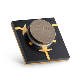
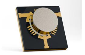
Typical Microstrip Circulator (Hzbeat 5–6 GHz class). Image source: hzbeat.com product page.
Hzbeat Typical Microstrip Circulator Overview
The series includes multiple T‑junction and Y‑junction realizations, with clockwise and counter‑clockwise variants. Models emphasize low insertion loss (≈0.5–0.7 dB), isolation ≈18–20 dB (band‑dependent) and broad temperature range (−55 °C to +85 °C).
Exact specifications, mechanical outlines and power ratings vary by band. Please refer to the detailed product tables on the Hzbeat product page.
Key Specifications & Bands
| Band (GHz) | Insertion Loss (dB) | Isolation (dB) | VSWR | Power (PK/CW, W) | Operating Temp (°C) |
|---|---|---|---|---|---|
| 2.7–4.0 | ~0.5–0.6 | ~18–20 | ≤1.3 | 20/10 | −55 – +85 |
| 3.5–5.0 | ~0.5–0.6 | ~18–20 | ≤1.25–1.3 | 20/10 | −55 – +85 |
| 4.8–8.0 | ~0.5–0.6 | ~18–20 | ≤1.25–1.3 | 20/10 | −55 – +85 |
| 5.0–6.0 | ~0.5 | ~20 | ≤1.25 | 20/10 | −55 – +85 |
| 7.0–9.5 | ~0.5–0.6 | ~17–18 | ≤1.3–1.35 | 20/10 | −55 – +85 |
| 8.0–18.0 | ~0.5–0.7 | ~16–20 | ≤1.25–1.4 | 20/10 (typ.), some higher bands 5/2 | −55 – +85 |
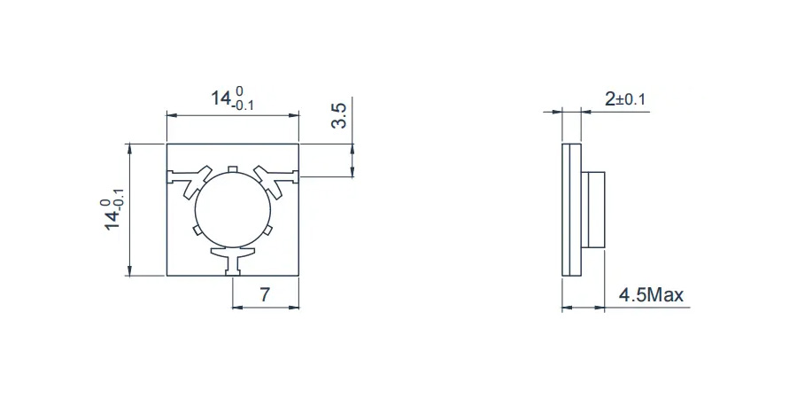
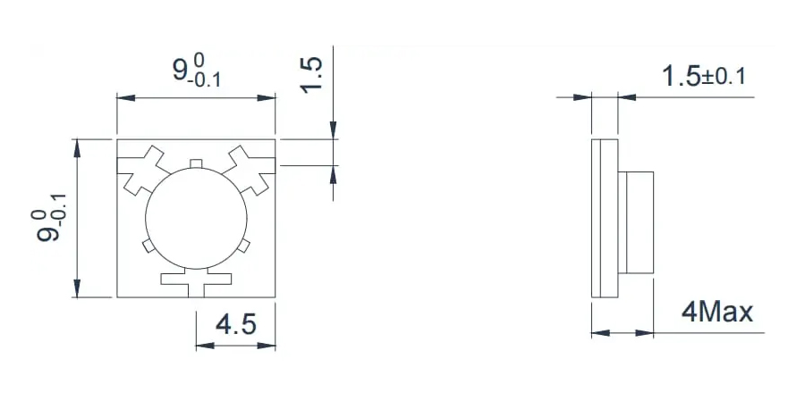
2.7–4.0 GHz T‑junction outline (typ.). Source: hzbeat.com.
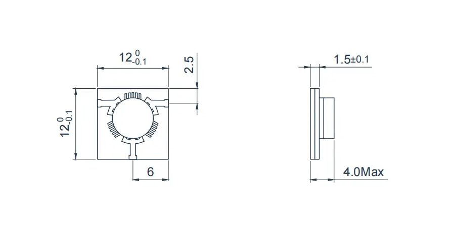
3.5–5.0 GHz T‑junction outline (typ.). Source: hzbeat.com.
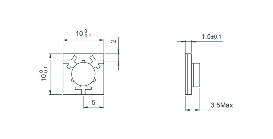
4.8–8.0 GHz T‑junction outline (typ.). Source: hzbeat.com.
5.0–6.0 GHz T‑junction outline (typ.). Source: hzbeat.com.
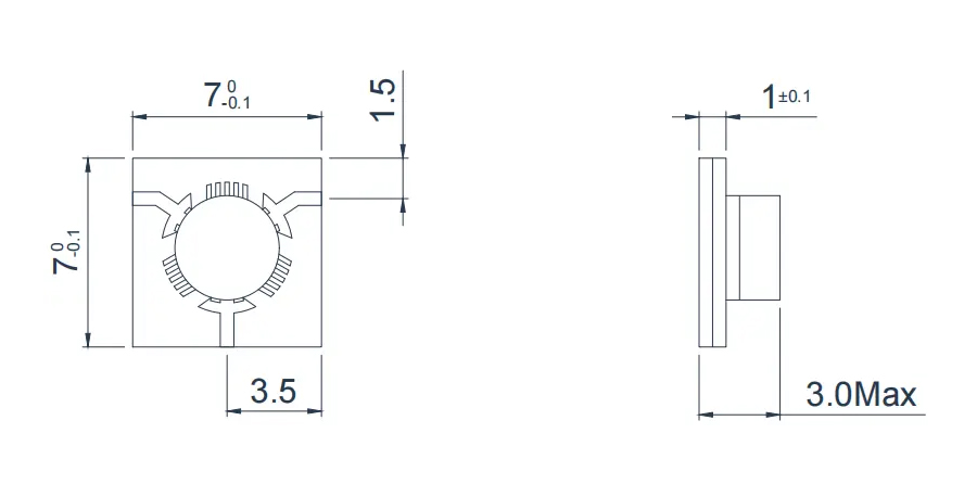
7.0–9.5 GHz T‑junction outline (typ.). Source: hzbeat.com.
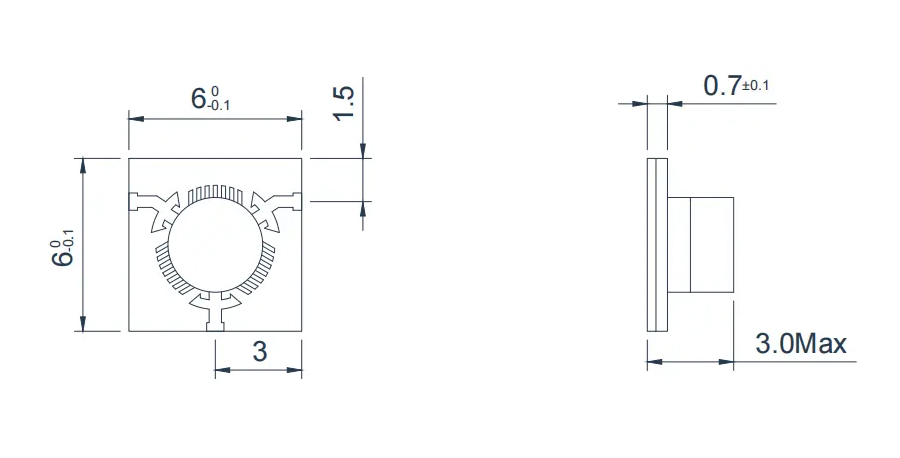
8.0–18.0 GHz T‑junction outline (typ.). Source: hzbeat.com.
Applications
- 5G / 5G‑Advanced radios (mid‑band, small‑cell)
- Radar front‑ends where SWaP matters (airborne, vehicular)
- Satellite ground terminals and up/down‑link chains
- Medical MRI and RF therapy equipment
- Industrial RF instrumentation and analyzers
Advantages
- Compact & light — Minimal spatial discontinuity when integrated with microstrip circuits; reliable 50 Ω bridging.
- Wide span — 2–40 GHz coverage across S/C/X/Ku/K/Ka bands.
- Consistent performance — Low insertion loss, stable isolation & VSWR across temperature.
- Direction options — CW and CCW variants available for each band.
References
- Hzbeat — Typical Microstrip Circulator page with specs & drawings.
- IEEE MTT literature on microstrip circulator design (for background theory).
Relateds


About the Author

HzBeat Editorial Content Team
Marketing Director, Chengdu Hertz Electronic Technology Co., Ltd. (Hzbeat)
Keith has over 18 years in the RF components industry, focusing on the intersection of technology, healthcare applications, and global market trends.