L-Band Isolators & Circulators: High-Isolation, Low-Loss RF Protection for Modern Microwave Systems
Updated on:
Keywords: L-band isolator,L band isolator,L-band circulator,L band circulator,L-band RF isolator,ferrite circulator,RF isolator,RF circulator,L-band radar,satcom front-end,low insertion loss,high isolation
How to design, select and qualify L-band isolators and L-band circulators for radar, satcom and navigation systems.
1. Why L-Band Isolators & Circulators Matter
In every serious microwave system there is a silent guardian: the L-band isolator or L-band circulator. These non-reciprocal RF components do not generate power or carry intelligence in the data stream, yet they are critical for keeping power amplifiers safe, receivers stable and antennas properly matched.
As radar, satellite communication and navigation systems move toward higher power density, tighter integration and more complex modulation schemes, the performance of the L band isolator or L-band RF circulator can decide whether a system behaves like a predictable instrument or an unstable black box.
- Prevents reflected power from damaging sensitive power amplifiers (PA) and LNAs.
- Improves system stability by absorbing mismatch and load variations.
- Reduces noise and spurious oscillations in L-band radar and satcom front-ends.
- Enables reliable long-term operation across temperature, vibration and humidity.
2. What Is an L-Band Isolator? What Is an L-Band Circulator?
An L-band isolator is a two-port, non-reciprocal RF device designed to transmit power from port 1 to port 2 while strongly attenuating any power flowing in the reverse direction. Technically speaking, it is usually a terminated ferrite circulator optimized for the 1 GHz to 2 GHz L-band range.
An L-band circulator is a three-port device that routes energy from port 1 to port 2, from port 2 to port 3 and from port 3 back to port 1, again in a single direction of rotation. At L-band, ferrite circulators are widely used as duplexers, T/R modules and antenna sharing elements.
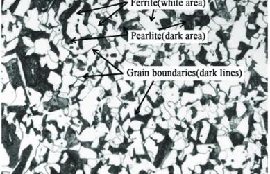
Both the L-band isolator and the L-band circulator rely on ferrite materials biased by a magnetic field. Under bias, the ferrite becomes gyromagnetic, making the propagation constant different in the forward and reverse directions. The result is non-reciprocity, which is the foundation of isolation in microwave components.
In practical RF design:
- The L-band isolator is placed at the output of a PA or at the input of a sensitive LNA.
- The L-band circulator often sits between the antenna and a combined transmit/receive chain.
- Combining both allows engineers to build robust L-band front-ends with shared antennas and high protection levels.
3. The Role of L-Band in Radar, Satcom & GNSS
The L-band, typically 1–2 GHz, occupies a unique sweet spot. Its wavelength, around 15–30 cm, penetrates clouds and rain better than higher-frequency bands, while still providing meaningful bandwidth. This makes L-band a natural choice for:
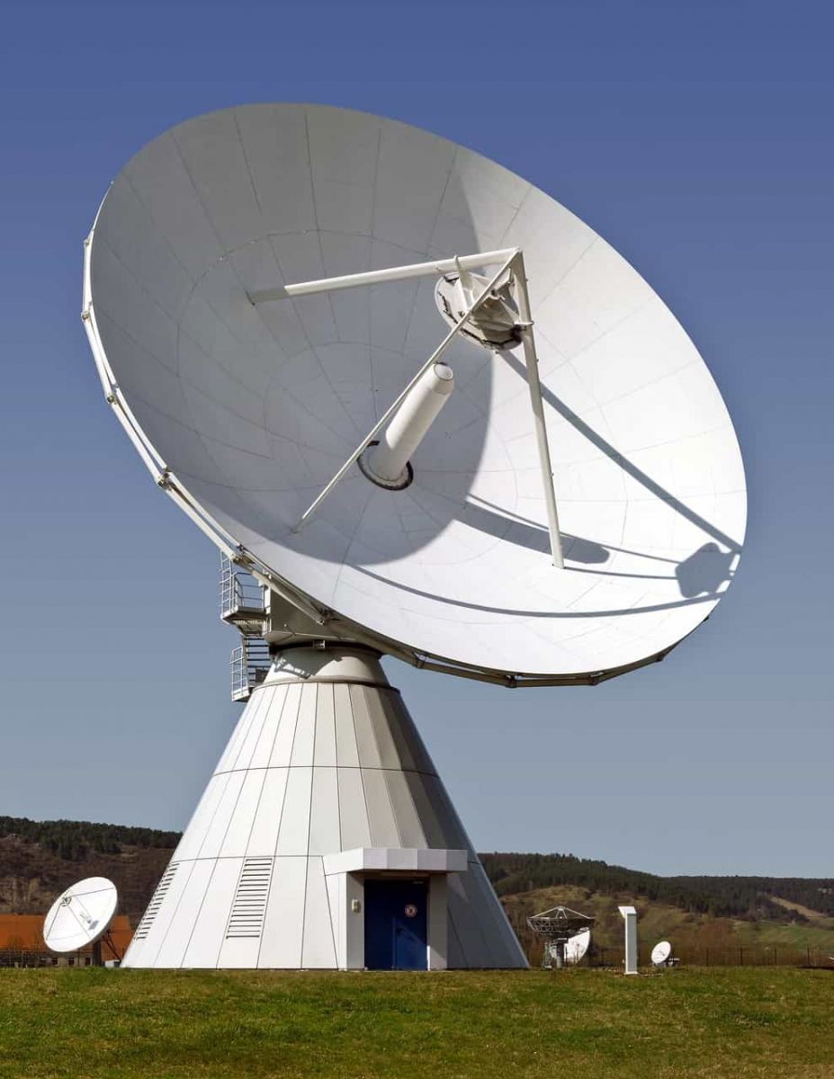
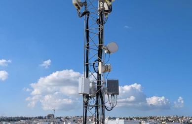
- L-band radar: long-range surveillance, air-traffic control and weather monitoring.
- GNSS systems: GPS, GLONASS, Galileo and other navigation constellations.
- Satellite communications: mobile satcom terminals, IoT satellites and safety-of-life links.
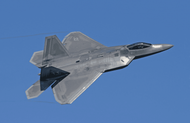
- Aviation and maritime communication: robust links that must survive rain fade and multipath.
In all these cases, L-band isolators and L-band circulators prevent reflected energy and load changes from degrading the link budget or destabilizing active components. For example, an L-band radar may transmit kilowatts of peak power into an antenna that is not perfectly matched across the scan angle or operating environment; the isolator absorbs the mismatch and protects the PA.
On the receive side, an L-band circulator can route signals from a shared antenna to a low-noise receiver, while a precision L-band isolator placed before a low-noise amplifier (LNA) ensures that impedance variations downstream do not disturb the optimized noise match.
4. Key RF Parameters for L-Band Isolators & Circulators
When engineers evaluate an L-band isolator or circulator, several RF parameters define whether the part is suitable for a given radar, satcom or GNSS design.
4.1 Insertion Loss (IL)
Insertion loss directly affects transmit efficiency and receive sensitivity. At L band, high-performance ferrite devices often target:
- Coaxial L-band isolator / circulator: typically 0.2–0.4 dB IL.
- Drop-in or microstrip L-band isolator: typically 0.25–0.6 dB IL.
Every 0.1 dB of additional IL steals margin from the link budget or forces the system designer to increase PA output power, size and heat dissipation. Low-loss L-band circulators are especially important in high-power radars and satcom solid-state power amplifier (SSPA) systems.
4.2 Isolation
Isolation tells you how effectively the L-band isolator blocks reflected power from returning to the source. Similarly, in an L-band circulator, isolation indicates how well unwanted reverse paths are suppressed.
- Baseline industrial designs offer about 18–22 dB isolation.
- Aerospace and defense programs often demand 23–30 dB or more across temperature.
4.3 VSWR / Return Loss
Good matching at every port minimizes ripple and standing waves. A quality L-band RF isolator or circulator typically targets:
- Return loss > 18–20 dB at all ports.
- Stable matching from the low end of L band to the high end (for example 1.0–1.7 GHz).
4.4 Power Handling
PAs in L-band radar and satcom can deliver tens or hundreds of watts. An L-band isolator installed at the PA output must survive:
- CW and peak power levels under full mismatch conditions.
- Continuous operation into 100% reflection across all phases, if specified.
- Thermal cycling over long mission lifetimes.
4.5 Temperature Range & Stability
Ferrite properties and magnet bias shift with temperature, so L-band isolators and circulators must be designed with careful material selection and magnetic circuit engineering. For airborne, marine and ground radar systems, operation from –40 °C to +85 °C or wider is common.
4.6 Size, Weight and Power (SWaP)
Modern platforms—from UAVs to handheld terminals—demand compact devices. Here, microstrip and SMT L-band isolators provide a path to:
- Reduced footprint on densely populated RF PCBs.
- Lower total weight in airborne and spaceborne applications.
- Automated assembly via reflow-compatible SMT packages.
5. Common Package Types: Coaxial, Drop-In, Microstrip & SMT
Different system architectures call for different mechanical interfaces. The most common L-band isolator and circulator package families are:
5.1 Coaxial L-Band Isolators & Circulators
Coaxial units use SMA, N-type or similar connectors. They are ideal for:
- High-power L-band radar transmitters and SSPAs.
- Outdoor satcom terminals and base stations.
- Laboratory test setups and prototypes.
5.2 Drop-In L-Band Isolators & Circulators
Drop-in designs bolt directly to a machined housing or T/R module. They offer a compact footprint and excellent thermal conduction. Many phased-array radar tiles depend on high-density drop-in L-band circulators to route signals efficiently.
For example, a designer might combine a drop-in L-band circulator with a separate high-power load to build a custom three-port L-band isolator that meets very specific power and bandwidth targets.
5.3 Microstrip and Stripline L-Band Isolators
Microstrip L-band isolators integrate directly onto RF PCBs and are attractive for GNSS front-ends and compact radios. Compared with coaxial styles they offer:
- Very small outline, suitable for high-density modules.
- Short lead lengths and low parasitics.
- Simplified routing to PAs, LNAs and filters.
To explore microstrip ferrite devices, you can refer to products such as microstrip circulators and similar PCB-based non-reciprocal components.
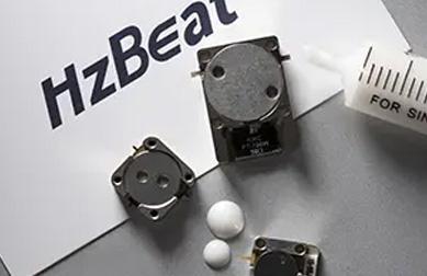
5.4 SMT L-Band Isolators
Surface-mount L-band isolators are optimized for automated assembly and reflow. They are typically used in high-volume communication modules, GNSS receivers and IoT gateways that need low-cost, compact protection.
For higher power or broader bandwidths, designers may still choose connectorized or drop-in circulator solutions combined with external terminations.
6. Practical Selection Framework for L-Band Isolator / Circulator Design-In
With many options on the market, choosing the right L-band RF isolator or L-band circulator can feel overwhelming. A simple, repeatable selection framework helps RF engineers decide quickly.
Step 1 — Define the RF Environment
Start by clearly defining:
- Operating band (for example 1.0–1.1 GHz GNSS, 1.2–1.4 GHz radar, 1.5–1.7 GHz satcom).
- Modulation type and peak-to-average power ratio.
- Expected VSWR at the antenna or load over frequency and temperature.
Step 2 — Set Insertion Loss and Isolation Targets
Based on the link budget and stability requirements, choose realistic but ambitious IL and isolation targets for the L-band isolator or circulator. High-end designs often aim for:
- Insertion loss ≤ 0.3–0.4 dB.
- Isolation ≥ 23–25 dB across the full operating band.
Step 3 — Choose Package and Interface
Decide whether a connectorized L-band isolator, a drop-in L-band circulator or a microstrip / SMT device is best suited. Consider thermal path, assembly flow and maintainability.
Step 4 — Verify Environmental and Reliability Requirements
For aerospace and defense systems, verify:
- Temperature range (for example –40 °C to +85 °C or higher).
- Vibration and shock levels.
- Outgassing, altitude and humidity requirements where applicable.
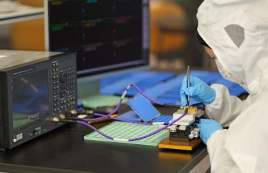
Step 5 — Evaluate Supplier Capability
The best L-band isolator or circulator is useless if it cannot be delivered consistently over the life of a program. When qualifying suppliers, engineers often look for:
- In-house ferrite processing and magnetic circuit design.
- Automated RF test and serialized S-parameter data.
- Support for custom center frequencies and bandwidths.
- Experience supplying L-band radar, satcom or GNSS programs.
For broader system coverage across bands, many engineers combine L-band components with higher-frequency devices such as coaxial circulators and waveguide circulators, building a complete non-reciprocal protection strategy from UHF through Ka-band.
7. Typical Engineering Pain Points & How to Avoid Them
Even experienced RF designers run into issues when integrating L-band isolators and circulators. The most common pain points include:
- Thermal drift: IL and isolation shift more than expected over temperature.
- Magnet aging: long-term bias changes slightly alter center frequency or return loss.
- Unexpected oscillations: PA stages oscillate when the circulator is connected due to layout or biasing issues.
- Mechanical stress: mounting stress detunes sensitive microstrip L-band isolators.
- Lead time and customization: standard parts do not match the exact L-band channel plan.
These risks can be mitigated by:
- Including margin in IL and isolation specs for worst-case temperature and tolerance.
- Designing robust mounting interfaces for drop-in and microstrip units.
- Simulating and measuring the complete chain (PA – isolator – filter – antenna) rather than just the individual component.
- Working with manufacturers who can adjust ferrite recipes, magnet bias and matching networks to your specific L-band window.
8. Example Architectures Using L-Band Isolators and Circulators
8.1 L-Band Radar Transmit / Receive Front-End
In a classic radar front-end, an L-band circulator connects the PA, the antenna and a receiver path. A terminated L-band isolator may also be used between the PA and the circulator to provide additional protection during antenna faults or maintenance conditions.
8.2 GNSS Front-End with L-Band RF Isolator
GNSS receivers typically operate at comparatively low power, but are sensitive to impedance changes and interference. A compact SMT L-band isolator can be inserted between the antenna filter and LNA to stabilize the impedance environment and block unwanted reverse signals from downstream circuitry.
8.3 Satcom SSPA Chain with Multiple L-Band Isolators
High-power satcom SSPAs often use several cascaded gain stages. Strategic placement of small, low-loss L-band RF isolators between stages helps prevent oscillations, while a rugged high-power L-band isolator at the final output protects against antenna VSWR faults.
8.4 Combining L-Band with Other Bands
Many platforms now combine L-band with S, C, X or Ka-band capability in one chassis. To keep these systems robust, designers mix L-band isolators and L-band circulators with higher-frequency non-reciprocal devices, sharing antennas or waveguide runs where appropriate.
9. FAQ: L-Band Isolators & Circulators
Q1. What is the difference between an L-band isolator and an L-band circulator?
An L-band isolator is a two-port device that passes power in one direction and absorbs it in the reverse direction. An L-band circulator is a three-port device that routes power sequentially from port 1 to 2, 2 to 3 and 3 back to 1. In practice, many L-band isolators are simply circulators with one port internally terminated in a matched load.
Q2. When should I use both an isolator and a circulator in the same L-band system?
In high-value or mission-critical systems, designers often place a rugged L-band isolator at the PA output and then use an L-band circulator toward the antenna. The isolator maximizes protection under fault or maintenance conditions, while the circulator enables antenna sharing between transmit and receive paths.
Q3. What insertion loss and isolation are realistic at L band?
For quality ferrite designs, it is common to see insertion loss around 0.25–0.4 dB and isolation in the 20–30 dB range across the specified L-band window. Exact values depend on bandwidth, power level, temperature range and package style.
Q4. Can L-band isolators and circulators be customized for non-standard frequencies?
Yes. Many manufacturers offer custom L-band RF isolator and L-band circulator designs with adjusted ferrite volumes, magnet bias and matching networks to center the response on non-standard frequencies or to widen/narrow the bandwidth to fit a specific radar or satcom channel allocation.
Q5. Are there non-ferrite alternatives to L-band isolators and circulators?
Research continues into non-magnetic approaches, such as switched transmission-line networks and time-varying metamaterials. While promising, these IC-compatible techniques are still emerging in commercial L-band radar and satcom markets. Ferrite-based L-band isolators and circulators remain the dominant choice for high-power, high-reliability systems.
10. References & Further Reading
- NASA Earthdata, Synthetic Aperture Radar (SAR) basics and the advantages of L-band radar for penetrating vegetation and clouds.
- Microwave engineering textbooks and application notes on ferrite isolators and circulators, covering non-reciprocity and S-parameter behavior.
- Vendor datasheets for L-band high-power isolators and circulators from established RF and microwave manufacturers, detailing typical insertion loss, isolation and power ratings.
- Research articles on stripline and microstrip ferrite circulator design, demonstrating compact, high-isolation L-band circulator topologies for integrated radar and communication modules.
- Industry white papers on space-qualified and avionics-grade L-band RF components, highlighting long-term stability, environmental testing and qualification standards.
Relateds
About the Author

HzBeat Editorial Content Team
Marketing Director, Chengdu Hertz Electronic Technology Co., Ltd. (Hzbeat)
Keith has over 18 years in the RF components industry, focusing on the intersection of technology, healthcare applications, and global market trends.