Broadband Microstrip Circulators by Hzbeat for 2–18 GHz RF Coverage
Updated on:
Keywords: broadband microstrip circulator, wideband rf isolator, spectrum monitoring, satcom
Introduction
Wideband radios, spectrum monitoring platforms, and next‑generation satcom terminals increasingly require single‑device coverage across multiple bands. Hzbeat’s broadband microstrip circulators are engineered to reduce part count while sustaining robust non‑reciprocity— protecting sensitive LNAs, stabilizing PA stages, and simplifying duplex/TPA paths from 2 up to 18 GHz depending on model.
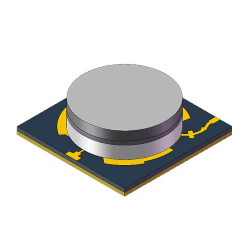
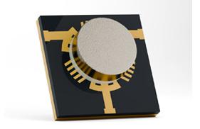
Broadband circulator render 1 (hzbeat.com).

Broadband circulator product 2 (hzbeat.com).
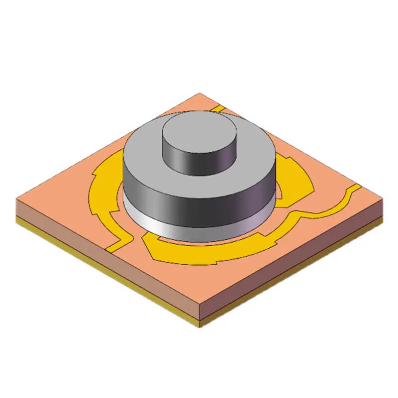
Broadband circulator render 3 (hzbeat.com).
Why Broadband Microstrip Circulators
Traditional narrowband approaches often chain multiple circulators to cover adjacent bands—costly in both BOM and board area. A broadband alternative collapses these into one qualified item, easing supply, qualification, and maintenance. For fielded systems where retrofits are expensive, broadband designs also extend useful life as band plans evolve.
Design Notes & Topologies
Hzbeat provides T‑junction and Y‑junction realizations with CW/CCW rotation options. T‑junctions tend to favor compact routing and straightforward layout; Y‑junctions can offer bandwidth and symmetry advantages depending on dielectric and ferrite stack parameters. Careful field shaping, via fencing, and bias configuration are used to maintain return loss and isolation across the wider passband.
Performance & Representative Specs
Representative parameters below illustrate typical envelopes observed in Hzbeat broadband microstrip circulators. Values vary by exact model; consult the product page for live datasheets and tolerances.
| Model (example) | Frequency (GHz) | Insertion Loss (dB) | Isolation (dB) | VSWR | PK/CW Power (W) |
|---|---|---|---|---|---|
| HMCTA20T60G‑B | 2.0–6.0 | ≤1.2 | ≥11 | 1.7 | - / 30 |
| HMCTB20T60G‑B | 2.0–6.0 | ≤1.2 | ≥11 | 1.7 | - / 30 |
| HMCTA60T180G‑B | 6.0–18.0 | ≤1.2 (6.0–6.5) | ≥11 | 1.7 | - / 30 |
| HMCTC80T120G‑B | 8.0–12.0 | ≤0.5 | ≥19 | 1.25 | 20 / 10 |
Note: Figures are indicative and band‑dependent. Power handling often declines with frequency; verify thermal paths and duty cycles.
Product Images
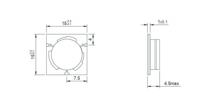
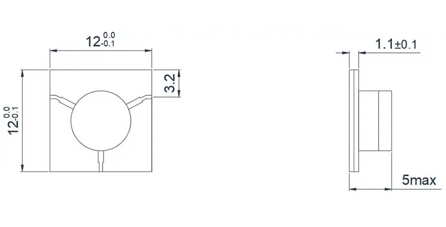
2.0–6.0 GHz T‑junction outline (hzbeat.com).
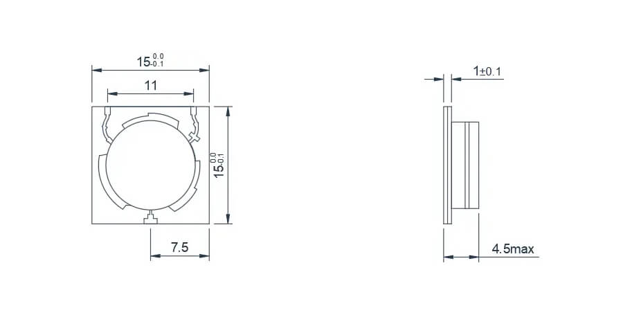
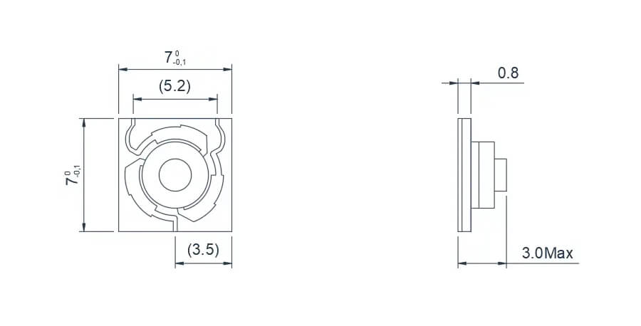
2.0–6.0 GHz Y‑junction outline (hzbeat.com).
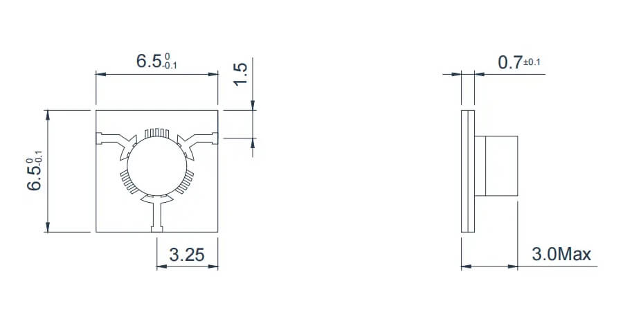
6.0–18.0 GHz T‑junction outline (hzbeat.com).
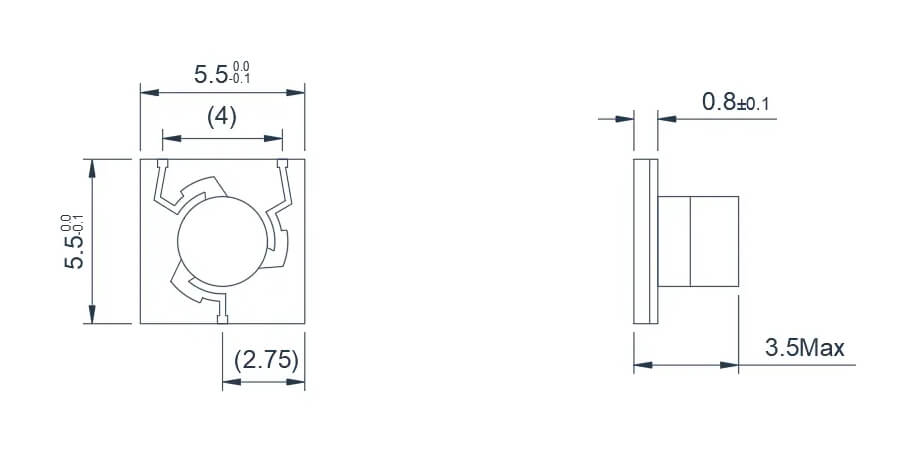
6.0–18.0 GHz Y‑junction outline (hzbeat.com).
8.0–12.0 GHz T‑junction outline (hzbeat.com).
8.0–18.0 GHz microstrip T‑junction outline (hzbeat.com).
Applications
- Spectrum Monitoring & RF Testing: Wideband coverage supports national monitoring systems and research labs.
- Satellite Communication: Reliable operation in Ku/Ka‑related lineups for ground stations and mobile terminals.
- Radar & Electronic Warfare: Multi‑band radar/EW chains leverage broadband devices to maintain isolation as waveforms and bands change.
Comparison with Typical / Miniaturized / SMT
- Broadband vs Typical: Broadband consolidates coverage; typical may offer lower loss on a narrower span.
- Broadband vs Miniaturized: Miniaturized prioritizes SWaP; broadband prioritizes coverage and flexibility.
- Broadband vs SMT: SMT favors mass‑production; broadband microstrip favors performance and configurability.
Market Outlook
As 5G/6G densify and NTN expands, demand grows for components that maintain performance across multiple bands with minimal redesign. Broadband microstrip circulators sit at this intersection—supporting research labs, test houses, satcom integrators, and defense programs.
Integration Tips
- Layout: Keep microstrip transitions short; use via fences near discontinuities; avoid right‑angle bends at ports.
- Thermal: Plan metal‑to‑chassis contact under the device where duty cycles are high; validate junction temperatures.
- Qualification: Request S‑parameters across temperature; define isolation targets at band edges, not just center frequency.
- Sourcing: Align on rotation (CW/CCW) and environmental envelope up front; consider VMI for long programs.
FAQ
Q1: Can a broadband unit replace several narrowband circulators?
Often yes, provided the required passbands fall within the device envelope and power/thermal margins are met.
Q2: What about isolation at the band edges?
Expect isolation to be specified across the full operating band; design for margins at the edges, where mismatch peaks may occur.
Q3: Are custom outlines or rotations available?
Hzbeat supports CW/CCW variants and can discuss outline adjustments—contact us with your constraints.
Links & Contact
Broadband Product Page · All Microstrip Circulators · Contact Hzbeat
Relateds


About the Author

HzBeat Editorial Content Team
Sara is a Brand Specialist at Hzbeat, focusing on RF & microwave industry communications. She transforms complex technologies into accessible insights, helping global readers understand the value of circulators, isolators, and other key components.