Drop-in RF Circulator Manufacturer and Supplier
Updated on:
Keywords: drop-in RF circulator manufacturer, RF circulator supplier, drop-in circulator China, microwave circulator factory, ferrite circulator, HzBeat RF components, radar SatCom 5G
High‑performance, compact solutions for L/S/C/X/Ku/Ka‑band radar, SatCom, and microwave subsystems.
1.Introduction
Drop‑in RF circulators are non‑reciprocal, three‑port devices that route energy directionally and shield sensitive components from reflected power. Their compact footprint and robust thermal path make them the preferred choice in front‑end modules, high‑density T/R units, and rugged field systems. In this technical brief, we unpack the design trade‑offs, material choices, S‑parameter behavior, thermal considerations, and reliability methodologies that separate commodity parts from mission‑grade components.
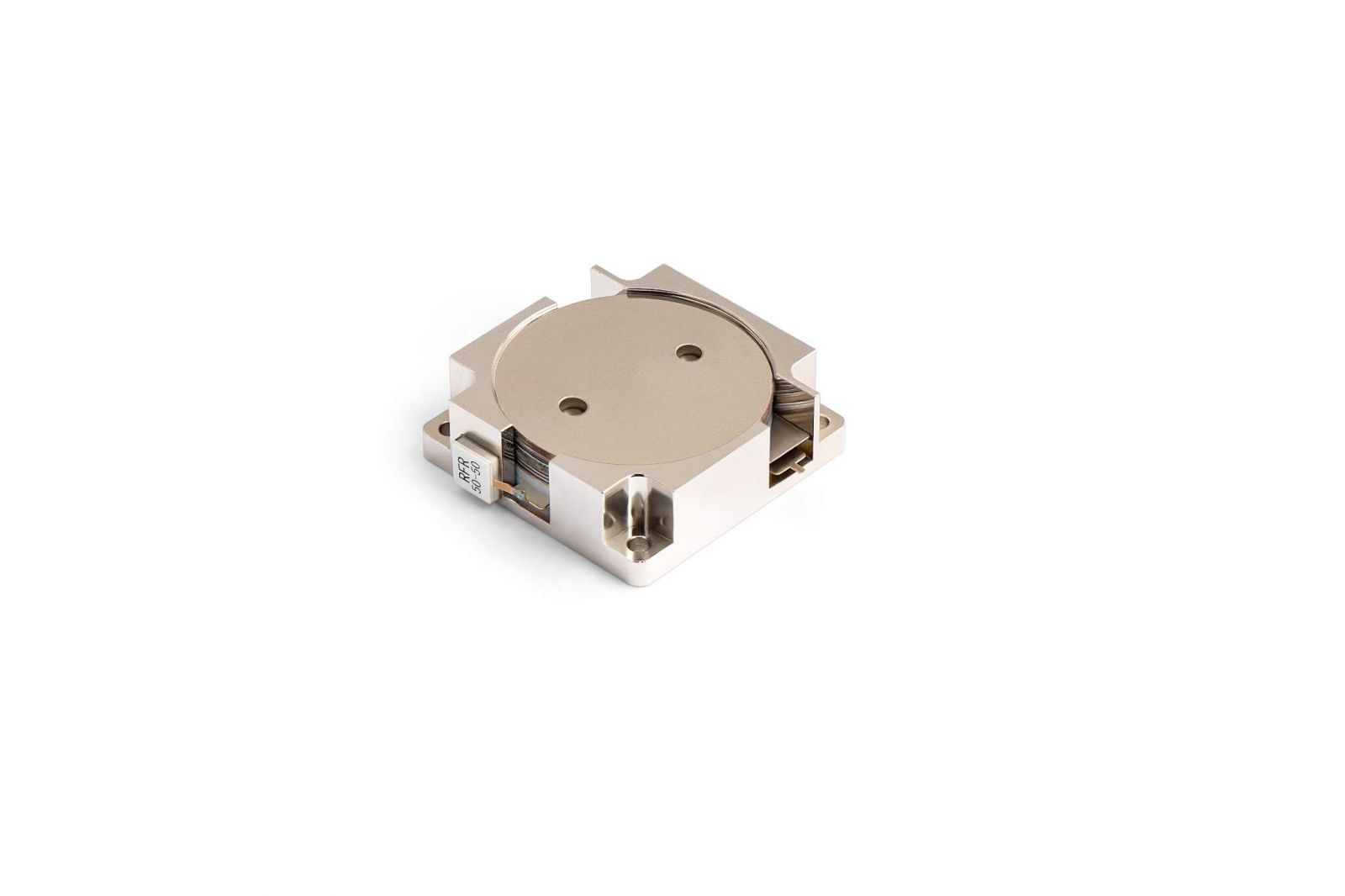
2.What Is a Drop‑in RF Circulator?
A drop‑in circulator integrates a ferrite resonator and a permanent‑magnet bias in a metal housing that “drops” into a cavity or carrier and fastens with screws. Electrical connection is typically realized via pins, tabs, or spring contacts that mate to a PCB or ceramic substrate. Compared with connectorized coaxial formats, drop‑ins cut out excess interconnects, reduce mismatch loss, and provide a short thermal path into the module chassis.
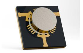
3.Ferrite Materials & Magnetic Design
At the heart of a circulator is a magnetized ferrite disk that supports non‑reciprocal propagation under a static magnetic field. Key material parameters include saturation magnetization Ms, linewidth ΔH, loss tangent, and Curie temperature Tc. For higher bands (X/Ku/Ka), low‑loss garnets or advanced spinel compositions are preferred to keep insertion loss down while preserving isolation.
- Bias Field: Usually provided by rare‑earth permanent magnets (e.g., SmCo for temperature stability, NdFeB for higher energy density).
- Temperature Effects: Magnet and ferrite drift with temperature; compensation strategies (material pairing, shims, or field‑trimming) are essential for spec stability.
- Bandwidth vs. Isolation: Increasing bandwidth often trades isolation flatness; careful resonator sizing and matching networks are required.
4.Electrical Performance & S‑Parameters
Circulators are typically characterized by S‑parameters referenced to 50 Ω. S21 denotes forward transmission (insertion loss), S11 and S22 capture input and output return loss (VSWR), while S31 quantifies isolation. Under power, self‑heating can shift the bias point; hence power‑swept S‑parameter measurements and load‑pull style stress tests are recommended.
| Band | Typical Frequency | Insertion Loss | Isolation | VSWR | Notes |
|---|---|---|---|---|---|
| L | 1–2 GHz | 0.25–0.35 dB | 23–28 dB | ≤1.25 | Robust power handling |
| S | 2–4 GHz | 0.3–0.4 dB | 22–26 dB | ≤1.3 | Common for radar altimeters |
| C/X | 4–12 GHz | 0.35–0.5 dB | 20–25 dB | ≤1.35 | Phased arrays, T/R modules |
| Ku/Ka | 12–40 GHz | 0.4–0.6 dB | 18–23 dB | ≤1.45 | Thermal design more critical |
Values above are representative and depend on specific geometry, matching, ferrite, and thermal environment. HzBeat offers trimming and band‑specific optimization.
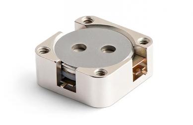
5.Thermal Management & Power Handling
Drop‑ins dissipate heat primarily through their metal base into the carrier or module chassis. Junction‑to‑case thermal resistance can be minimized with a lapped base, high‑conductivity interface (e.g., graphite pad, grease), and adequate clamp force. For pulsed radar, transient power can be substantial; average and peak limits must be specified along with duty cycle and pulse width.
- Baseplate Flatness: Improves thermal contact and RF planarity.
- Heatsinking: Tie the circulator base to a machined heat spreader or the module wall.
- Derating Curves: Specify power vs. ambient/case temperature for mission profiles.
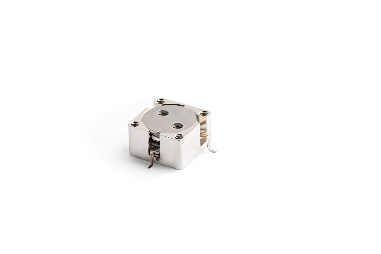
6.Mechanical Integration & PCB Mounting
Because drop‑ins live inside the RF chain, mechanical and RF layouts must be co‑designed. Minimize discontinuities at port transitions, keep ground returns tight, and use short, wide traces or launch pins to reduce inductance. EMI gaskets and cover lids help ensure isolation between adjacent channels in dense T/R modules.
- Mounting Pattern: Use symmetric screw layout to maintain pressure uniformity.
- RF Launch: Tabs, pins, or spring contacts should interface directly to 50 Ω microstrip or stripline.
- Shielding: Partition walls between ports mitigate coupling in multi‑channel assemblies.
7.Manufacturing & Calibration Flow
- Ferrite & Magnet Prep: Material inspection (Ms, ΔH), magnetization, and tolerance control.
- Assembly: Resonator placement, matching network, housing alignment.
- Bias Adjust: Field trimming or shimming for center‑frequency lock.
- Calibration: VNA‑based S‑parameter sweep across temperature points.
- Screening: Outlier removal under environmental stress.
8.About HzBeat — Miniaturized & Ultra‑Wideband RF Solutions (20 MHz–200 GHz)
HzBeat is a Chengdu‑based high‑tech manufacturer of non‑reciprocal RF/microwave components. We design and build drop‑in, microstrip, coaxial, and waveguide circulators/isolators spanning 20 MHz–200 GHz, with a focus on ultra‑wideband performance, miniaturized form factors, and production‑ready integration.
- Ultra‑Wideband Coverage: Flat isolation and low insertion loss across multi‑octave bands from sub‑GHz to mmWave.
- Miniaturization: Low‑profile housings, high‑energy magnet bias, and tight RF launches for high‑density T/R modules and compact terminals.
- Customization: Tailored bands, footprints, thermal paths, and power handling for radar, SatCom, 5G/6G, and T&M applications.
- Manufacturing in Chengdu: Automated assembly, in‑house ferrite processing, and mmWave VNA calibration under ISO 9001 with RoHS/REACH materials.
- Brand Mission: “Connecting frequencies in the world.”
9.Reliability, Qualification & Compliance
For fielded platforms, qualification is as important as nominal RF performance. HzBeat applies mission‑oriented test plans drawn from MIL‑STD and IEC practices.
- Thermal cycling & high‑temp storage
- Random vibration & shock
- Humidity & salt fog
- 100% VNA verification
- Power‑burn & load endurance
- Long‑term drift monitoring
- ISO 9001 quality system
- RoHS/REACH material declarations
- Full device datasheet & COC
10.Applications & Mini‑Case Studies
1) X‑Band Phased‑Array Radar
In a T/R module, a drop‑in circulator isolates the LPA (linear power amplifier) from antenna mismatch and adjacent element coupling. With isolation > 22 dB and IL ≤ 0.5 dB, sidelobe levels remain controlled and calibration overhead decreases. Thermal derating ensures safe operation during high‑duty search modes.
2) Ka‑Band SatCom User Terminal
Compact terminals favor drop‑ins due to their low profile and direct chassis heatsinking. Wideband matching supports multi‑carrier traffic, while tight VSWR improves EIRP and link margin under rain fade conditions.
3) Test & Measurement Coupling Networks
Drop‑ins simplify fixture design by removing connectors inside the signal path. Repeatable fixturing improves guardbanding in automated production test.
11.Format Comparison
| Format | Pros | Cons | Best Use |
|---|---|---|---|
| Drop‑in | Compact; good thermal path; low interconnect loss | Requires custom mounting; careful RF launch design | T/R modules, terminals, compact front‑ends |
| Microstrip | Lowest height; PCB‑integrated | Power handling limited by substrate; thermal path thinner | Lightweight radios, integrated MMIC chains |
| Coaxial | Plug‑and‑play; easy lab rework | Bulky; connector loss; higher BOM | Bench test, modular systems |
| Waveguide | Ultra‑low loss at mmWave; high power | Large; heavier; alignment critical | Backhaul, radar front‑ends at very high power |
12.Procurement Checklist
- Target band, bandwidth, and center frequency
- Insertion loss, isolation, VSWR at temperature corners
- Average/peak power, duty cycle, pulse specs
- Mechanical envelope, mounting pattern, RF launch type
- Operating/storage temperature and environment
- Compliance needs (RoHS/REACH, COC, screening level)
- Lead time, lot‑to‑lot variability, traceability
13.Emerging Trends & Future Directions
- mmWave Expansion: Wider adoption at Ka/Q/V‑bands with low‑loss garnets.
- Thermal Innovations: Advanced bases (Cu‑Mo composites) for pulsed power.
- Array‑Scale Co‑Design: Circulator specs aligned with digital calibration budgets.
- Supply Chain Resilience: Multi‑source materials and magnets for stability.
14.Conclusion
Drop‑in circulators deliver the mix of size, efficiency, and robustness demanded by modern microwave systems. With disciplined material engineering, bias design, and thermal architecture, they protect front‑ends, preserve linearity, and safeguard link budgets. HzBeat manufactures and calibrates drop‑ins from sub‑GHz through Ka‑band and beyond, supporting custom footprints, tuned bandwidths, and mission‑level screening — ready for integration into your next radar, SatCom, or test platform.
15.FAQ
- Q1. How do I size isolation for my PA and antenna mismatch?
- Start from the worst‑case return loss at the antenna and the PA’s allowable reflected power. Work backward to an isolation target with temperature margin and process spread.
- Q2. Can a drop‑in replace a coaxial circulator 1:1?
- Functionally yes, but mechanical and RF launches differ. Expect a brief redesign of the mounting cavity and matching to realize the performance benefits.
- Q3. What screening level is typical for airborne platforms?
- Depending on the program, thermal cycling, random vibration, 100% VNA, and extended burn‑in are common; consult your qualification plan.
- Q4. Do you offer non‑magnetic alternatives?
- For some architectures, non‑magnetic isolation (e.g., active/reciprocal solutions) may be evaluated, but ferrite circulators remain the most power‑robust option today.
Relateds


About the Author

HzBeat Editorial Content Team
Sara is a Brand Specialist at Hzbeat, focusing on RF & microwave industry communications. She transforms complex technologies into accessible insights, helping global readers understand the value of circulators, isolators, and other key components.