Why Is RF Circulator Bandwidth Limited?
Learn why RF circulator bandwidth is limited by ferrite materials, resonance, impedance matching, junction geometry, magnetic bias, and temperature. Discover how HzBeat designs broadband and custom RF circulators for demanding microwave systems.
 Updated on: Jul 17, 2026
 Author:
An RF circulator has limited bandwidth because its non-reciprocal behavior, impedance matching, ferrite material properties, and physical junction dimensions are all frequency-dependent. A circulator can provide low insertion loss, high isolation, and good return loss only within the frequency range where these factors work together correctly.
Outside the designed frequency band, the ferrite junction may no longer produce the required phase relationship between the RF signals. At the same time, impedance matching becomes less effective, causing insertion loss to increase, isolation to decrease, and VSWR to deteriorate.
What Determines the Bandwidth of an RF Circulator?
The usable bandwidth of an RF circulator is mainly influenced by the following factors.
1. Ferrite Material Characteristics
Ferrite material is the core element that enables a circulator to route signals in one direction.
When a DC magnetic field is applied to the ferrite, the material creates a non-reciprocal electromagnetic response. However, ferrite permeability and magnetic behavior change with frequency. The required gyromagnetic response is therefore strongest only within a particular frequency region.
If the operating frequency moves too far from the designed range:
- The ferrite phase response changes.
- Signal rotation inside the junction becomes less accurate.
- Insertion loss may increase.
- Isolation between ports may decrease.
- Return loss and VSWR may become worse.
Different ferrite formulations have different saturation magnetization, linewidth, dielectric constant, temperature stability, and loss characteristics. Selecting the correct material is therefore one of the most important steps in broadband circulator design.
2. Resonant Operating Principle
Many ferrite circulators operate around a carefully designed electromagnetic resonance.
The ferrite disk, junction geometry, magnetic bias, and transmission-line structure are tuned so that signals entering one port combine constructively at the desired output port and destructively at the isolated port.
This condition is frequency-sensitive. When the frequency changes, the phase relationship between the electromagnetic modes also changes. Once the phase difference moves outside the acceptable range, the isolated port can no longer remain well isolated.
This is one reason a circulator cannot maintain identical performance over an unlimited frequency range.
3. Impedance-Matching Limitations
A circulator must usually be matched to a system impedance of 50 ohms.
The matching structure may include:
- Transmission-line transformers
- Stepped-impedance sections
- Matching capacitors
- Tuning elements
- Microstrip patterns
- Stripline transitions
- Waveguide matching structures
These matching elements are frequency-dependent. A matching network optimized for the center frequency will generally provide its best return loss over a limited range.
As the operating frequency moves away from the center frequency, impedance mismatch increases. This can result in higher reflected power, poorer VSWR, additional insertion loss, and reduced isolation.
Broadband designs require more complex matching structures, but additional matching sections can also increase product size, manufacturing difficulty, and sensitivity to dimensional tolerances.
4. Junction Geometry
The dimensions of the circulator junction are closely related to wavelength.
Important dimensional factors include:
- Ferrite disk diameter and thickness
- Junction width
- Transmission-line length
- Port angle and symmetry
- Air-gap dimensions
- Grounding structure
- Housing dimensions
- Waveguide or coaxial transitions
Because wavelength changes with frequency, a junction optimized for one frequency range may not support the correct electromagnetic field distribution at another frequency.
At higher frequencies, even a very small machining or assembly deviation can produce a noticeable electrical change. This makes it more difficult to maintain wide bandwidth, especially in compact microwave and millimeter-wave circulators.
5. Higher-Order Electromagnetic Modes
As frequency increases, unwanted higher-order modes may appear inside the ferrite junction, transmission line, connector transition, or metal housing.
These modes can cause:
- Resonance peaks
- Isolation notches
- Insertion-loss ripple
- Unstable return loss
- Unexpected coupling between ports
A broadband circulator must suppress these unwanted modes throughout the entire operating band. This often requires electromagnetic simulation, careful cavity design, precise grounding, and tight control of mechanical dimensions.
6. Magnetic Bias Stability
The permanent magnet or external bias field determines the operating condition of the ferrite material.
If the magnetic field is not uniform or stable, the circulator performance may shift across frequency. Magnetic bias can also be affected by:
- Magnet material
- Temperature
- Mechanical spacing
- Magnetic circuit design
- Ferrite consistency
- Nearby magnetic materials
A well-designed magnetic circuit helps stabilize the operating band, but the ideal bias condition still covers only a limited frequency range.
7. Temperature Effects
Ferrite properties, permanent magnet strength, dielectric constants, and metal dimensions can all change with temperature.
As a result, the circulator’s center frequency and matching condition may shift. A product that performs well at room temperature may show higher insertion loss or lower isolation at very high or very low temperatures.
For applications such as aerospace, radar, satellite communication, defense electronics, and outdoor base stations, bandwidth should be evaluated across the full required temperature range rather than only at room temperature.
Why Is Wideband Circulator Design More Difficult?
A wider operating band means the circulator must maintain several parameters simultaneously across a larger frequency range:
- Low insertion loss
- High isolation
- Low VSWR
- Good return loss
- Stable phase response
- Adequate forward and reverse power handling
- Temperature stability
Improving one parameter can affect another. For example, a matching structure that improves low-frequency return loss may reduce high-frequency isolation. A smaller junction may improve miniaturization but increase power density and thermal stress. A wider matching network may increase bandwidth but also increase size and manufacturing complexity.
Therefore, wideband circulator design is not simply a matter of changing the ferrite disk or increasing the magnet strength. It requires coordinated optimization of the ferrite material, magnetic circuit, transmission-line structure, impedance matching, mechanical housing, thermal design, and manufacturing tolerances.
Does Circulator Structure Affect Bandwidth?
Yes. Different circulator structures have different bandwidth capabilities and design constraints.
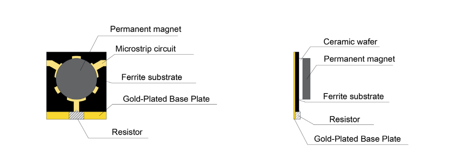
Microstrip Circulators
Microstrip circulators are compact, lightweight, and suitable for integration into RF modules. However, conductor loss, substrate characteristics, grounding, and radiation effects can limit broadband performance, especially at higher frequencies.
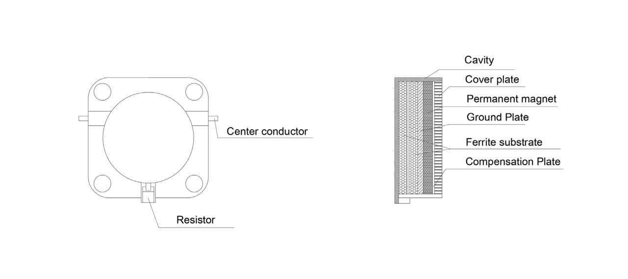
Drop-In Circulators
Drop-in circulators use stripline-style transmission structures and are widely used in radar, communication, and amplifier modules. They can provide a good balance among bandwidth, power handling, size, and integration flexibility.
Coaxial Circulators
Coaxial circulators include connectorized interfaces and metal housings. Their overall bandwidth depends not only on the ferrite junction but also on the coaxial transitions, connectors, internal matching structures, and housing resonances.
Waveguide Circulators
Waveguide circulators are commonly used in high-frequency and high-power systems. Their bandwidth can be limited by waveguide dimensions, junction resonances, ferrite loading, matching structures, and the cutoff frequencies of unwanted modes.
No single structure is best for every bandwidth requirement. The appropriate structure should be selected according to frequency, fractional bandwidth, power, insertion loss, isolation, size, temperature, and installation method.
Can an RF Circulator Cover Multiple Frequency Bands?
A single circulator may cover adjacent frequency ranges when the required total bandwidth is technically achievable. However, covering widely separated bands, such as a large portion of L band and S band, can be much more difficult.
The feasibility depends on:
- Lowest and highest operating frequencies
- Required fractional bandwidth
- Minimum isolation
- Maximum insertion loss
- Return-loss or VSWR requirement
- Power level
- Product size
- Temperature range
- Circulator structure
When the required bandwidth is too wide, it may be more practical to use two circulators optimized for separate frequency bands rather than forcing one component to cover the entire range.
How Can RF Circulator Bandwidth Be Increased?
Manufacturers may improve bandwidth by using:
- Broadband ferrite materials
- Optimized ferrite dimensions
- Multi-section impedance matching
- Stepped transmission-line structures
- Improved magnetic bias design
- Broadband connector or waveguide transitions
- Electromagnetic field simulation
- Higher-precision machining
- Tighter material and assembly tolerances
- Temperature-compensated designs
However, a wider bandwidth may involve trade-offs in insertion loss, isolation, power capacity, physical size, cost, and production complexity.
For this reason, the required bandwidth should be specified together with the complete electrical and environmental requirements.
How Should I Specify the Required Bandwidth?
When requesting an RF circulator, do not provide only a center frequency or a general band name. A complete specification should include:
- Exact frequency range
- Maximum insertion loss
- Minimum isolation
- Maximum VSWR or minimum return loss
- Forward power
- Reflected or reverse power
- CW and peak power conditions
- Operating temperature
- Connector or mounting type
- Circulation direction
- Size limitations
- Pulse width and duty cycle, when applicable
For example, “S-band circulator” is not sufficiently precise because S band covers a broad frequency range. A requirement such as 2.7–3.1 GHz, insertion loss ≤0.4 dB, isolation ≥20 dB, VSWR ≤1.25, and forward power of 100 W CW gives the manufacturer enough information to evaluate feasibility.
How Does HzBeat Support Broadband RF Circulator Requirements?
HzBeat develops and manufactures microstrip, drop-in, coaxial, waveguide, and dual-junction ferrite circulators and isolators, with product capabilities covering frequencies from approximately 20 MHz to 200 GHz across different product series.
For broadband and customized requirements, HzBeat can evaluate the complete RF system conditions rather than considering frequency alone. The design process may include:
- Ferrite material selection and optimization
- Electromagnetic simulation of the junction
- Magnetic bias and magnetic-circuit design
- Broadband impedance-matching optimization
- Connector, microstrip, stripline, or waveguide transition design
- Power and thermal evaluation
- Precision mechanical processing
- S-parameter testing and performance verification
- Customization according to size and installation requirements
HzBeat’s integrated process—from material research and precision manufacturing to testing and validation—helps control the factors that influence bandwidth, including ferrite consistency, dimensional tolerances, magnetic-field stability, assembly accuracy, and test repeatability.
For demanding applications, customers are encouraged to provide the complete frequency range, insertion loss, isolation, VSWR, power, temperature, size, and interface requirements. HzBeat can then determine whether a standard broadband model is suitable or whether a customized RF circulator is required.
Conclusion
The bandwidth of an RF circulator is limited because ferrite behavior, electromagnetic resonance, impedance matching, junction geometry, magnetic bias, and mechanical transitions all vary with frequency.
A wider bandwidth is possible, but it normally requires more advanced ferrite selection, matching structures, electromagnetic optimization, precision manufacturing, and stricter tolerance control. It may also involve trade-offs among insertion loss, isolation, power handling, size, and cost.
The best approach is to define the actual operating range and system requirements clearly, then select or customize a circulator that provides stable performance throughout the entire required band.
 Article Tags
Keith Wong
Marketing Director, Chengdu Hertz Electronic Technology Co., Ltd. (Hzbeat)
Keith has over 18 years in the RF components industry, focusing on the intersection of technology, healthcare applications, and global market trends.