High-Power, High-Performance RF Circulators & Isolators for Microwave Systems
Updated on:
Keywords: high power RF circulator, high power RF isolator, high-performance circulator, high isolation, microwave systems, radar, SatCom, 5G, waveguide circulator, coaxial circulator, RF duplexer
1. Why high-power RF circulators & isolators matter
As microwave systems move toward higher transmit power, wider bandwidth and denser integration, the role of high-power RF circulators and isolators becomes more critical than ever. These passive, non-reciprocal devices sit quietly in the RF chain, but they determine whether a radar transmitter survives a mismatch, whether a SatCom gateway meets its EIRP target, and whether a 5G macro base station can keep radiating at full power without burning out its PA.
In this article, we look at how high-power, high-performance RF circulators and isolators work in real microwave systems, what “high power” actually means, how to interpret key specifications like insertion loss and isolation, and how to choose the right technology (waveguide, coaxial, drop-in, or microstrip) for your use case.
2. Basics: what RF circulators & isolators actually do
An RF circulator is a passive, non-reciprocal three- or four-port microwave device that routes energy from one port to the next in a fixed rotational direction (e.g. Port 1 → Port 2 → Port 3 → Port 1). This behavior is realized using ferrite materials biased by a static magnetic field in a carefully designed junction geometry. It allows transmit and receive paths to share a common antenna while maintaining isolation between them in radar, SatCom and communication systems.
An RF isolator is essentially a circulator with one port internally terminated in a matched load. From the outside it appears as a two-port device: it passes energy in the forward direction with low loss but strongly attenuates energy flowing backward. That makes high-power RF isolators ideal for protecting sensitive power amplifiers (PAs) against reflections due to antenna mismatch or rapidly changing loads.
In high-power microwave systems, both components act as protection and stability elements:
- Circulators – duplexing between transmitter, receiver and antenna, or routing power between multiple branches.
- Isolators – absorbing reflected power and preventing oscillation, gain compression or failure in the PA.
3. What “high-power” really means in microwave systems
- Average power in the tens of watts up to kilowatts (kW) for continuous-wave (CW) operation.
- Peak power in pulsed radar or communication systems that can be 10–100× higher than average power.
- High VSWR conditions at the antenna or load, sometimes up to 3:1 or worse during tuning, rain fade or fault scenarios.
- Elevated ambient and case temperatures, especially inside compact transmitter racks or radomes.
A robust high-power RF circulator or isolator has to survive not only the nominal forward power but also:
- Reflected power – when the antenna or load is mismatched or disconnected.
- Thermal cycling – long-term heating and cooling during on/off cycles.
- Environmental stress – vibration, humidity, altitude and sometimes pressurization in airborne or shipborne systems.
4. Key performance parameters to watch
High-power, high-performance RF circulators and isolators are defined by a set of core specifications. For microwave system engineers, these numbers are not just datasheet lines – they directly translate to link budget, reliability and lifetime.
4.1 Power handling (CW and peak)
Always distinguish between:
- CW / average power – the continuous power level the device can dissipate without exceeding its temperature limits.
- Peak power – short pulses (µs–ms) used in radar or pulsed communication; limited by ferrite saturation and electric field breakdown.
4.2 Insertion loss
Insertion loss (typically 0.2–0.6 dB for high-performance devices in narrow bands) directly reduces system efficiency. In high-power transmitters, every tenth of a dB lost in the circulator or isolator becomes heat that must be removed through the housing and heat sink, increasing cooling requirements and operating cost.
4.3 Isolation
Isolation quantifies how well the non-reciprocal device prevents reverse signal flow between ports. High-power RF isolators in front of PAs often target >20 dB isolation across the operating band, and specialized designs can exceed 30 dB. Higher isolation means:
- Better PA protection under mismatch.
- Lower risk of oscillation in high-gain RF chains.
- Improved dynamic range in duplexed receivers.
4.4 VSWR / return loss
VSWR (or return loss) at each port is critical in high-power systems. A high VSWR at the circulator/isolator interface can create standing waves and local hotspots. High-performance devices are typically specified with VSWR ≤ 1.25:1 or ≤ 1.3:1 across the band to keep reflections under control.
4.5 Bandwidth and frequency range
High-power ferrite circulators and isolators can be designed for:
- Narrowband high-power operation (e.g. a specific radar band).
- Broadband coverage (multi-standard or agile radios) at somewhat lower power density.
There is always a trade-off between bandwidth, insertion loss, isolation and size. As bandwidth increases, achieving the same low loss and high isolation becomes more challenging and generally requires more complex junction design and carefully optimized ferrite material.
4.6 Linearity and intermodulation
In high-power multi-carrier systems (e.g. SatCom or 5G macro sites), linearity and passive intermodulation (PIM) performance also matter. Poor PIM performance in a high-power RF circulator or isolator can create unwanted spurs in-band, degrading receiver sensitivity or violating spectral masks.
5. High-power technologies & form factors
Different mechanical platforms are used for high-power RF circulators and isolators, depending on frequency, power level, and system architecture.
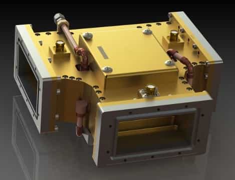
5.1 Waveguide circulators & isolators
Waveguide circulators and isolators are the workhorses for very high power in microwave bands. They offer:
- Very low insertion loss thanks to low conductor and dielectric loss in the waveguide.
- Excellent power handling due to large cross-section and high breakdown voltage.
- Good thermal conduction via robust metal housings that can be bonded to heat sinks or cooled surfaces.
These devices are widely used in long-range radar, high-power SatCom gateways, and high-power test benches where kW-level RF power is common.
5.2 High-power coaxial circulators & isolators
Coaxial circulators and isolators are built around a ferrite junction with coaxial interface transitions. High-power coaxial designs are commonly found in:
- Cellular base stations and microwave backhaul links.
- Medium-power SatCom uplinks.
- Laboratory and production test systems.
They provide a convenient connectorized format (N-type, 7-16 DIN, 4.3-10, etc.) with good power handling and moderate footprint, making them popular in rack-mount RF amplifier systems and outdoor radio units.
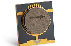
5.3 Drop-in and microstrip solutions
For compact, integrated microwave modules and T/R front-ends, drop-in and microstrip circulators/isolators offer a smaller footprint. While they typically handle less power than large waveguide or coaxial units, modern ferrite and magnet technology enables surprisingly high power density in:
- Multi-layer drop-in circulators mounted to a carrier or cold plate.
- Microstrip or stripline circulators integrated in T/R modules for AESA radar.
- SMT (surface-mount) microstrip circulators for compact RF front-ends.
When power levels increase, these miniaturized devices often work together with external heat spreading, metal-core PCBs, or direct-bonded copper substrates to keep junction temperatures within the ferrite’s safe operating range.
6. Design considerations for high-power, high-performance operation
6.1 Ferrite material and magnetic bias
High-power RF circulators and isolators rely on carefully selected ferrite materials with appropriate saturation magnetization, linewidth, and loss tangent. The external magnet (permanent magnet or electromagnet) must provide a stable bias field across temperature, ensuring the desired non-reciprocal behavior over the full operating range.
6.2 Thermal path and mechanical design
Because all insertion loss turns into heat, the thermal path from the ferrite and termination load to the outside world is crucial:
- Use of high-conductivity metals (copper alloys, aluminum) for junction and housing.
- Direct bolting to heat sinks or cold plates for high-power waveguide and coaxial units.
- Thermal interface materials or solder preforms to minimize contact resistance.
In high-power isolators, the internal load must be designed to safely dissipate reflected power under worst-case VSWR, often with derating curves specified over temperature.
6.3 Managing reflections and mismatch
Even the best high-power device will fail if system-level reflections are not considered. Best practices include:
- Specifying a maximum system VSWR under all operating conditions.
- Placing isolators as close as practical to the PA output.
- Using high-quality connectors, transitions and waveguide flanges to minimize additional mismatch.
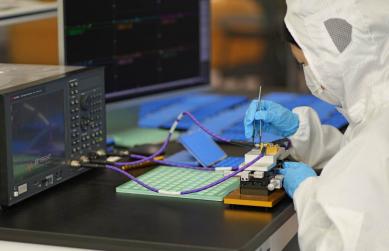
6.4 Environmental and reliability testing
High-power RF circulators and isolators for mission-critical radar, defense, or infrastructure systems are typically qualified through:
- Thermal cycling and high-temperature operating life (HTOL).
- Vibration and shock tests for airborne, naval, or mobile platforms.
- Humidity, salt fog and corrosion testing for outdoor environments.
These tests verify that non-reciprocal performance – and especially isolation – remains stable over the device’s lifetime.
7. Typical applications of high-power RF circulators & isolators
High-power, high-performance RF circulators and isolators are central to many microwave systems:
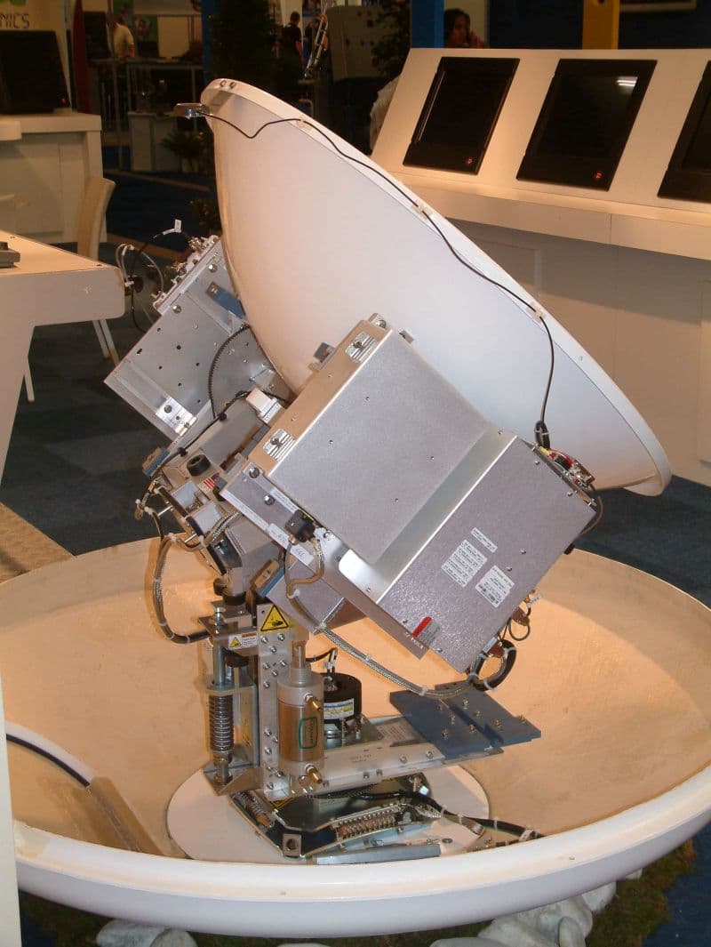
- Radar systems – Duplexing between a high-power transmitter and a sensitive receiver that share a common antenna; protecting the receiver from the transmit pulse.
- Active phased array (AESA) T/R modules – Per-element circulators and isolators manage transmit and receive paths and protect solid-state PAs.
- SatCom gateways and VSAT hubs – High-power uplink chains use circulators/isolators to stabilize high-gain amplifier stages and protect them from reflections due to weather or misalignment.
- 5G/6G base stations and microwave backhaul – High-power coaxial circulators/isolators in outdoor radio units and high-power amplifiers improve system robustness and reduce downtime.
- High-power RF test and measurement – Test benches and EMC/EMI facilities require robust non-reciprocal components to safely dissipate reflected power when devices under test are mismatched or fail.
8. How to specify the right high-power RF circulator or isolator
When you define a high-power RF circulator or isolator for a microwave design, capture at least the following parameters in your specification:
- Frequency band and bandwidth – e.g. 1.2–1.4 GHz, 8–12 GHz, 27–31 GHz; and required fractional bandwidth.
- Average and peak power – including duty cycle and pulse width, if applicable.
- Maximum VSWR / mismatch conditions – at both the source and the load sides.
- Insertion loss and isolation targets – across the full operating band and temperature range.
- Form factor and interfaces – waveguide type, connector type (N, 7-16, 4.3-10, SMA, K, etc.), drop-in or microstrip pad geometry.
- Operating temperature range – including hot-spot predictions near the ferrite and internal terminations.
- Size and weight constraints – especially important in airborne and space applications.
- Environmental and reliability requirements – shock, vibration, humidity, altitude, MTBF targets.
A clear, quantitative specification helps the manufacturer optimize ferrite selection, junction design, housing, and thermal management so the final product meets both power and performance requirements without excessive size or cost.
9. Conclusion
High-power, high-performance RF circulators and isolators are more than “just” passive components. They are the guardians of modern microwave systems, quietly absorbing reflections, enforcing directionality and protecting high-value power amplifiers and receivers under demanding conditions.
By understanding how these devices handle power, how key parameters like insertion loss, isolation, VSWR and bandwidth interact, and how different platforms (waveguide, coaxial, drop-in, microstrip) trade power against size and integration, system engineers can design microwave links that are both robust and efficient – ready for the next generation of radar, SatCom, 5G/6G and test applications.
10. FAQ: High-Power RF Circulators & Isolators
Q1. How do I choose between a waveguide, coaxial, or drop-in circulator for high-power systems?
It depends primarily on power level, bandwidth, and integration needs. Waveguide circulators are best for kilowatt-class microwave systems. Coaxial circulators suit tens to hundreds of watts for radar, SatCom, and 5G amplifiers. Drop-in and microstrip designs target compact T/R modules with moderate power but tight integration.
Q2. What isolation level is considered “high performance” for high-power RF isolators?
Most high-power microwave systems require at least 20 dB isolation, while premium designs achieve 25–30 dB. Higher isolation means better amplifier protection and improved system stability.
Q3. How much mismatch (VSWR) can a high-power isolator safely tolerate?
Quality high-power RF isolators typically handle VSWR up to 2.0:1–3.0:1. Severe mismatch increases thermal load, so isolators must be selected with proper reflected-power derating curves.
Q4. What causes failure in high-power RF circulators?
Common causes include ferrite overheating, saturation under high peak pulses, termination burnout, and mechanical stress. Poor heatsinking, excessive insertion loss, or unexpected antenna mismatch are major contributors.
Q5. Can high-power RF circulators support wideband operation?
Yes—although increasing bandwidth typically increases insertion loss and complicates magnetic biasing. High-power broadband applications use advanced ferrites and optimized junctions to maintain both power and performance.
Q6. Where are high-power circulators and isolators most commonly used?
They are heavily used in radar, SatCom gateways, 5G/6G radio units, microwave backhaul, AESA T/R modules, and high-power RF test benches.
Q7. What parameters should I prioritize for system-level optimization?
Focus on insertion loss, isolation, CW/peak power rating, thermal resistance, and VSWR. These directly determine efficiency, PA lifetime, and system robustness.
Explore More Products
RF Circulators
Complete range of coaxial, waveguide, and drop-in circulators for high-reliability applications.
View All ModelsRF Isolators
Superior isolation and low insertion loss performance to protect your transmitters and amplifiers.
View All ModelsRelateds


About the Author

HzBeat Editorial Content Team
Sara is a Brand Specialist at Hzbeat, focusing on RF & microwave industry communications. She transforms complex technologies into accessible insights, helping global readers understand the value of circulators, isolators, and other key components.