What Is the Purpose of an RF Isolator
Updated on:
Keywords: RF isolator purpose, RF isolator function, microwave isolator, protect power amplifier, VSWR protection, ferrite isolator, RF circulator, radar, SatCom, MRI
In every serious RF or microwave system, you will eventually ask a simple but critical question: what is the real purpose of an isolator? It is not just another passive box in the rack. A ferrite RF isolator is a non‑reciprocal two‑port device that lets energy flow in one direction while strongly attenuating reverse power.
In practice, that means the isolator sits between a sensitive source (typically a power amplifier or low‑noise module) and an unpredictable load (antenna, duplexer, filter, test port), quietly doing three things:
- Protecting the amplifier from reflected power and high VSWR events,
- Stabilizing gain, noise figure and linearity against load variations,
- Improving measurement and system accuracy by enforcing a “clean” source impedance.
1. What an RF Isolator Actually Does
An ideal isolator can be thought of as a directional, lossless one‑way valve for RF power. Real devices exhibit finite insertion loss in the forward path and a specified isolation value in the reverse path, e.g. 0.3–0.5 dB forward loss and 20–25 dB isolation for L‑/S‑band ferrite designs commonly used in radar and SatCom front ends.
1.1 Core functions
- VSWR protection: When the antenna or downstream network presents a poor match (high VSWR), part of the forward power is reflected. The isolator diverts this reverse power into an internal termination instead of back into the power amplifier.
- Stabilization: Many high‑gain, broadband PAs and LNAs are conditionally stable. Load‑dependent impedance variations at their output can cause oscillation or gain ripple. The isolator “decouples” the active device from those variations, presenting a more constant load over frequency, temperature and time.
- Isolation between stages: In multi‑channel or multi‑carrier systems, isolators reduce undesired coupling through common loads or combiners, limiting intermodulation and crosstalk.
1.2 How it works (non‑reciprocal ferrite physics)
Most microwave isolators are implemented as three‑port ferrite circulators with one port terminated internally. A ferrite puck is biased by a DC magnetic field so that RF propagation becomes non‑reciprocal: power entering Port 1 rotates to Port 2, but power entering Port 2 is rotated to Port 3 (the matched load), not back to Port 1.
From a system perspective, this non‑reciprocity is the key: forward power sees low loss, reverse power sees high attenuation and a matched termination.
2. Why Isolators Are Critical in Modern RF Chains
As frequencies move into C‑band, X‑band and Ka‑band and as systems adopt wideband, multi‑carrier modulation schemes, the tolerance for mismatch and instability shrinks dramatically. In that context, isolators are no longer “optional accessories” but risk‑control components.
2.1 Protecting high‑power amplifiers
In radar transmitters, satcom gateways or 5G macro radios, the RF power amplifier is one of the most expensive and fragile components. Severe mismatch can cause:
- Over‑voltage at the output device, leading to junction breakdown;
- Over‑current and thermal runaway under high reflected power;
- Bias and feedback loop instability when the load impedance shifts abruptly.
By inserting an isolator between the PA and antenna interface, most of the reflected energy is absorbed in a robust, well‑cooled termination rather than inside the semiconductor die.
2.2 Stabilizing sensitive receivers and transceivers
In low‑noise receivers, mixers, and frequency synthesizers, small changes in impedance can move oscillation poles, change loop gain, or degrade noise figure. An isolator at the output of the LNA or local oscillator:
- Reduces standing waves caused by cable harnesses, switches, or filters;
- Helps maintain a predictable 50 Ω environment for calibration;
- Minimizes pulling and pushing of VCOs due to load variations.
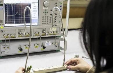
2.3 Enabling repeatable measurements
In production test or field service, engineers want the test setup—not the device under test—to dominate system uncertainty. Using an isolator in front of a spectrum analyzer, power meter, or receiver can:
- Improve measurement repeatability when testing poorly matched devices,
- Protect test equipment inputs from accidental over‑power or mismatch,
- Reduce the sensitivity of calibration to cable movements and connector wear.
3. Typical Application Scenarios
3.1 Radar transmit/receive modules
In pulsed and FMCW radar, isolators are widely used:
- At the output of the transmitter PA to survive antenna arcing, icing, or moving targets near the aperture;
- Between stages inside T/R modules to prevent oscillation when phase shifters and attenuators switch;
- In test couplers and calibration loops to linearize the behavior of the measurement path.
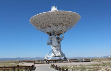
3.2 Satellite communication gateways and VSAT terminals
High‑power uplink chains operating in C‑, Ku‑, Ka‑ or Q/V‑band rely on isolators between the HPA/SSPA and the up‑converter or OMT. Benefits include:
- Protection during antenna mis‑pointing, rain fade or waveguide icing,
- Reduced intermodulation when multiple carriers share a common HPA,
- Improved availability and reduced unplanned downtime for outdoor units.
3.3 Medical MRI and industrial RF heating
MRI transmit coils and RF heating applicators often present complex, time‑varying loads due to patient motion or process changes. Isolators in these systems:
- Protect the RF power chain from rapid load excursions,
- Improve patient and equipment safety by limiting uncontrolled power reflections,
- Help maintain consistent field strength and image quality or heating profiles.
4. Key Electrical Parameters that Define an Isolator’s Purpose
| Parameter | Typical Value | Why It Matters |
|---|---|---|
| Frequency range | e.g. 1.2–1.4 GHz (L‑band), 8–12 GHz (X‑band), 26–40 GHz (Ka‑band) | Must fully cover the operating band including modulation sidebands and guard bands. |
| Insertion loss | 0.25–0.8 dB, depending on band and technology | Directly reduces available output power and affects NF in receive paths. |
| Isolation | ≥20–25 dB (standard), ≥30 dB (high‑isolation types) | Defines how much reflected power is prevented from returning to the source. |
| VSWR | <1.20:1 to <1.35:1 typically | Good match at all ports is required so the isolator doesn’t introduce new reflections. |
| Power handling | From a few watts to kilowatt‑class CW or pulsed | Must exceed both forward power and any credible reflected power scenario. |
| Temperature range | –40 °C to +85 °C (commercial/industrial), or wider for defense/space | Ferrite bias and magnetic properties are temperature‑dependent; isolation and loss drift must remain acceptable. |
5. How to Decide Whether You Really Need an Isolator
Because isolators add cost and insertion loss, RF designers sometimes try to omit them. A pragmatic checklist:
- Is your PA or LNA sensitive to load pulling or oscillation? If yes, an isolator is often the simplest stabilizing element.
- Are you dealing with high peak or average power? The higher the power, the more dangerous even moderate reflections become.
- Is the load well‑controlled? A fixed, well‑matched filter bank is safer than a rotating antenna, slip‑ring, or long outdoor feeder that can be damaged or detuned.
- Are field repairs expensive or impossible? For remote satellite gateways, radar sites or space payloads, the cost of a failure is far higher than the cost of a good isolator.
6. FAQ: Common Questions About RF Isolators
Q1. Is an isolator the same as a circulator?
Not exactly. A circulator is a three‑port non‑reciprocal device where power “circulates” from Port 1→2, 2→3 and 3→1. An isolator is usually a circulator with the third port internally terminated, effectively creating a two‑port one‑way device.
Q2. Can I use a directional coupler plus load instead of an isolator?
In some low‑power or narrowband cases, a coupler and external termination can approximate isolation. However, the resulting reverse isolation is usually much lower than that of a dedicated ferrite isolator, and the assembly is bulkier and more sensitive to layout. For high‑power or wideband systems, a purpose‑built isolator is usually preferred.
Q3. Does an isolator improve overall system efficiency?
No—the isolator itself introduces forward loss. Its value lies in protecting expensive components, reducing unplanned downtime, and maintaining linearity and accuracy. Viewed over the life‑cycle of a radar, base station or gateway, those benefits usually outweigh the small static loss penalty.
Q4. Where should I place the isolator in the block diagram?
The most common position is directly at the output of the power amplifier or sensitive active stage. In some architectures, additional isolators are used at the outputs of LNAs, driver PAs, frequency converters, or distribution splitters to prevent unwanted coupling between branches.
Relateds

About the Author

HzBeat Editorial Content Team
Sara is a Brand Specialist at Hzbeat, focusing on RF & microwave industry communications. She transforms complex technologies into accessible insights, helping global readers understand the value of circulators, isolators, and other key components.