Insertion Loss vs Isolation: Key Trade-Offs in RF Circulator Design
Updated on:
Keywords: insertion loss,isolation,RF circulator design,radar systems,5G,satellite communication,RF isolator supplier
Engineers rarely get both extremes at once. This guide explains why insertion loss and isolation pull in different directions—and how to choose the right balance for radar, 5G, satellite, and MRI.
1. Introduction
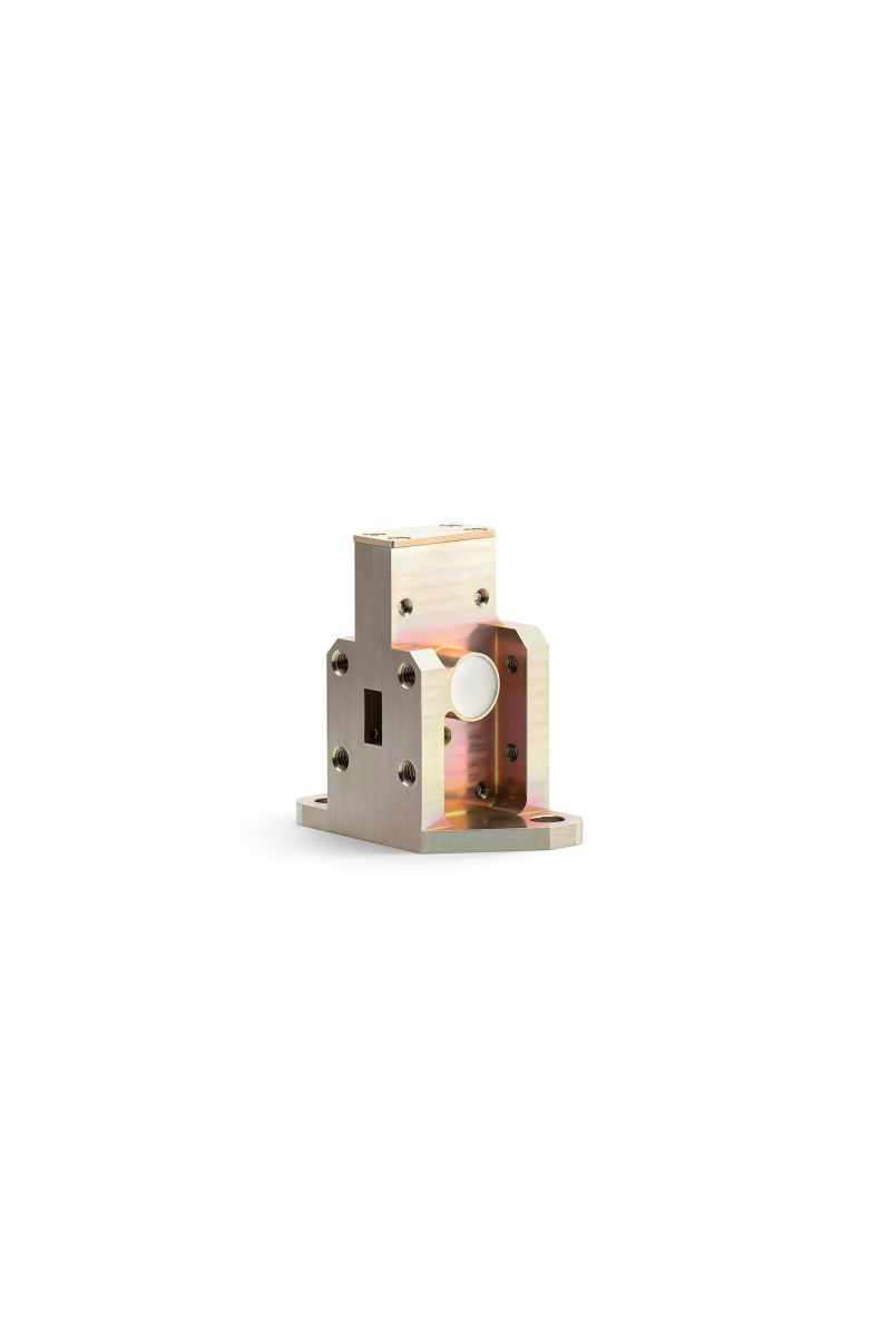
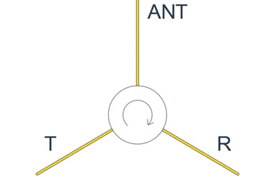
RF circulators are non-reciprocal three-port devices that stabilize duplex operation, route transmit power, and shield sensitive receivers. They underpin modern systems from phased-array radar and 5G base stations to satellite payloads and MRI coils. In practice, designers must juggle multiple figures of merit; among them, insertion loss (IL) and isolation (Iso) form the most consequential push-pull pair. Lower IL boosts efficiency and link margin; higher Iso prevents reverse leakage and receiver desensitization. No single geometry or material stack “wins” across all axes—context is king.
2. Understanding Insertion Loss
Definition. Insertion loss is the forward attenuation when a signal traverses the low-loss path of a circulator, typically reported in dB. It captures conduction, dielectric, magnetization, and interface losses across the junction and matching networks.
Typical engineering targets. High-performance microstrip or drop-in circulators often aim for ≈0.2–0.5 dB IL over their specified band; broadband coaxial parts may run higher depending on bandwidth and connectorization. Every 0.1 dB matters in link budgets—especially near the edge of coverage or in small-cell uplinks.
System impact. In cellular and fixed wireless planning, IL directly subtracts from the link margin budget; on the bench, you’ll see IL stack with cable and connector losses, while OTA path loss dominates at mmWave. Keeping IL small extends coverage and reduces PA stress.
Related reading and parts: Drop-in Circulators, Coaxial Circulators.
3. Understanding Isolation
Definition. Isolation quantifies how well reverse energy is rejected between non-adjacent ports (e.g., TX leakage into RX). In two-port isolators (internally terminated circulators), it’s the attenuation in the high-loss direction.
Typical engineering targets. Commercial parts frequently deliver ≈20–25 dB isolation; aerospace and defense gear push into ≈30–40 dB with tighter tolerances, larger volumes, or waveguide embodiments. Higher Iso limits LNA saturation and protects delicate mixers in high-EIRP or pulsed transmit chains.
Practical note. Isolation is frequency- and temperature-sensitive. Bias drift, ferrite dispersion, and assembly tolerances can erode Iso at band edges—budget margin accordingly.
Related reading and parts: Waveguide Isolators.
4. Why IL and Isolation Are Trade-Offs
4.1 Material physics
Lower IL favors low-loss ferrites and minimal metal/ferrite interfaces; higher Iso often demands stronger bias, thicker ferrite, tight matching, or multi-section impedance transforms—all of which can add dissipation or mismatch.
4.2 Geometry & packaging
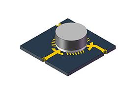
Compact microstrip Y-junctions minimize path length (good for IL) but may trail coaxial or waveguide units in ultimate isolation. Waveguide designs can achieve very high Iso at the cost of size and mass; drop-in formats strike a middle ground for many radar and satcom payloads.
4.3 Frequency realities
At Ku/Ka-band, machining and ferrite dispersion tolerances tighten. Designers usually trade a few tenths of a dB in IL to secure stable isolation across temperature and process spread.
Rule of thumb:
If your receiver sensitivity is the bottleneck (e.g., long-range radar), bias toward isolation. If coverage/efficiency dominates (e.g., 5G macro or FWA), bias toward low IL. Mixed constraints (e.g., Ka-band satcom) call for a balanced target and thermal headroom.
5. Application-Driven Design Choices
5.1 Phased-Array Radar
Priority: Isolation. TX leakage can desensitize the LNA chain and raise the detection threshold. Waveguide or high-volume drop-ins with ≳30 dB Iso are common, with careful thermal and bias control in pulsed, high-duty environments.
5.2 5G/6G Base Stations & FWA
Priority: Low IL. Each tenth of a dB compounds with cables, duplexers, and combiners. When operating at 26–39 GHz, OTA loss dominates; nevertheless, shaving device IL helps PA back-off and site energy budgets.
5.3 Satellite Communications
Priority: Balanced. Space payloads need IL discipline to preserve EIRP/G/T while maintaining enough Iso to protect ultra-low-noise receivers—across radiation, vacuum, and thermal extremes.
5.4 Medical MRI & Scientific
Priority: Both. Extremely low received signals make isolation vital; at the same time, any loss ahead of the first LNA degrades SNR. Thermal stability and repeatability matter as much as the headline specs.
6. Optimization Approaches
6.1 Material & bias engineering
Select low-loss ferrites with appropriate saturation magnetization; design for uniform bias across the disk or posts; budget thermal drift. These choices set the ceiling for IL and Iso simultaneously.
6.2 Matching & multi-section networks
Stub-tunes, dielectric loading, or multi-resonator transitions can lift isolation—at the price of added sensitivity and possible IL penalties. Tune with realistic conductor/dielectric loss models.
6.3 Architecture & system co-design
Consider circulator + isolator combos where reverse protection is paramount; or redistribute gain/noise to accommodate a few tenths of a dB IL if it secures robust Iso and bandwidth.
6.4 Customization
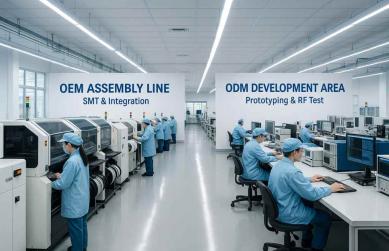
Requirements rarely fit a catalog line. ODM workflows can lock the right IL/Iso point for a band (L/S/X/Ku/Ka), power class, and duty cycle—while packaging (microstrip/drop-in/coaxial/waveguide) aligns with thermal and mechanical realities.
ODM inquiries: Hzbeat RF Circulators & Isolators.
7. Market Outlook & Supplier Landscape
Macro drivers—5G densification and FWA, sat-broadband constellations, radar modernization, and high-end medical imaging—are expanding demand for low-IL devices with robust isolation at higher bands. The center of gravity is shifting toward integration (smaller footprints, thermal-aware stacks) and application-specific IL/Iso tuning rather than single-number hero specs.
8. Conclusion
No free lunch: insertion loss and isolation are coupled by materials, geometry, and frequency. The “best” circulator is the one whose IL/Iso point is right for the job: radar leans isolation, RAN leans IL, satcom and MRI balance both with margin. Start from the system budget, then back-solve the device targets—and validate across temperature, bias, and process corners.
9. FAQ
Q1: Why can’t I get ultra-low IL and ultra-high Iso simultaneously?
Because the same changes that raise isolation—thicker ferrite, stronger bias, multi-section matching—tend to increase dissipation or mismatch, lifting IL. The physics enforces a compromise.
Q2: What feels “excellent” for X-band radar?
As a ballpark, ≈0.3 dB IL with ≳30 dB Iso across the operational bandwidth is a strong result, assuming thermal/bias stability and manufacturability.
Q3: Packaging impact?
Microstrip/drop-in minimize footprint and IL; coaxial adds ruggedness and bandwidth; waveguide reaches the highest isolation and power handling—at size/mass cost.
10. References
- ESCIES, “Basic Facts About Circulators & Isolators,” definitions of IL and isolation, and fundamentals.
- Marzall & Popović, “Microstrip Ferrite Circulator Design With Control of Ferrite Behavior,” University of Colorado—trade-offs among return loss, isolation, bandwidth.
- EDN, “Link-budget calculations needed for 5G OTA testing”—practical loss stacking and mmWave context.
- NASA NTRS reports on ferrite circulators—typical IL/Iso figures and temperature behavior.
- Qorvo (Microwave Journal reprint), “5G FWA Array and RF Front-End Trade-Offs”—system-level trade thinking.
- PMC (2024), “Design of X-Band Circulator and Isolator for High-Peak-Power Applications”—spec envelopes in X-band.
- Hzbeat Official Site: RF Circulators & Isolators.
Relateds
About the Author

HzBeat Editorial Content Team
Marketing Director, Chengdu Hertz Electronic Technology Co., Ltd. (Hzbeat)
Keith has over 18 years in the RF components industry, focusing on the intersection of technology, healthcare applications, and global market trends.