Which RF Circulator Type Offers the Widest Bandwidth?
Updated on:
Keywords: RF circulator, wideband circulator, broadband circulator, microstrip circulator, stripline circulator, drop-in circulator, coaxial circulator, waveguide circulator, insertion loss, isolation, VSWR, 5G, radar, SatCom
An engineering-first look at microstrip/stripline (drop-in), coaxial, and waveguide circulators — what truly drives usable bandwidth, and how to choose for 5G, radar, and satellite systems.
1) What is an RF Circulator?
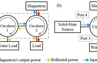
An RF circulator is a passive, non-reciprocal three-port device that routes energy directionally: power entering Port-1 exits Port-2, Port-2 to Port-3, and Port-3 back to Port-1. This one-way traffic provides isolation between transmitter and receiver chains, protects power amplifiers from mismatch, and enables duplex architectures. The non-reciprocal behavior is achieved using ferrite materials under a DC magnetic bias, leveraging gyromagnetic effects (e.g., Faraday rotation) in carefully tuned junctions.
While the ideal textbook circulator would offer constant, ultra-low insertion loss and very high isolation across unlimited bandwidth, real designs must balance bandwidth against insertion loss (IL), isolation (ISO), return loss (RL), power handling, size, weight, and cost.
2) Main Types & Where Bandwidth Comes From
Three packaging/implementation families dominate the market:
- Planar: Microstrip and stripline (often delivered as drop-in parts) for PCB-level integration and small form factors.
- Coaxial: With SMA/N/7-16/DIN or similar connectors for modular system builds and flexible cable interconnects.
- Waveguide: Flanged components optimized for high frequency and high power with very low losses.
In practice, “widest bandwidth” can mean two things: (i) the absolute fractional bandwidth around a center frequency, or (ii) the breadth of product families available across many distinct bands. Planar and coaxial lines often excel at (ii) because they scale across sub-GHz to mmWave with appropriate ferrite, matching, and packaging. Waveguide shines at very high frequency and power with superb IL/ISO in its band, but isn’t a single hardware form factor that conveniently spans from VHF to mmWave.
3) What Limits Circulator Bandwidth?
Usable bandwidth is gated by:
- Ferrite material & biasing: Saturation magnetization, linewidth, temperature stability, and uniform magnetic bias control the non-reciprocity and losses over frequency.
- Junction geometry: Y-junction, stripline junction, and hybrid coupler styles each trade matching ease, isolation flatness, and manufacturability.
- Matching networks: Broadband RL requires clever, often multi-section, low-Q networks with tight tolerance control.
- Packaging & interfaces: Coax connector bandwidth/VSWR, PCB stack-up (Dk/Df), ground via fencing, and waveguide flange precision all matter.
- Thermal & power behavior: High power induces self-heating; ferrite properties, glue layers, and magnet circuits must remain stable across the full band.
Tips:
Rule of thumb: the broader you push bandwidth, the more carefully you must watch IL ripple, isolation floor, and VSWR at the band edges—especially in compact planar builds.
4) Type-by-Type Bandwidth Comparison
| Type | Bandwidth Potential | Typical Strengths | Typical Trade-offs | Best-fit Use Cases |
|---|---|---|---|---|
| Microstrip / Stripline (Drop-in) | Excellent fractional bandwidth within a chosen band; scalable from sub-GHz to mmWave with proper ferrite and matching. | Small, light, PCB-integrated, cost-effective at scale; easy to co-design with filters/PA/LNA on the same board. | Lower power than waveguide; broadband matching is sensitive to PCB stack-up and tolerance; thermal design is critical. | 5G RU/DU, small cells, phased arrays, compact radios, test modules. |
| Coaxial | Very broad portfolio coverage across many bands; practical broadband performance with familiar connectors. | Modular, serviceable, good power handling; easier lab integration; flexible cable routing. | Bulkier and heavier than planar; connector choice can limit top-end frequency and RL. | Benchtop, subsystems, radios with cabling, field-replaceable modules, higher-power terrestrial links. |
| Waveguide | Outstanding in-band performance at microwave/mmWave; ultra-low IL, high ISO; wide fractional bandwidth within its waveguide band. | Top-tier IL/ISO and power; ideal for radar and SatCom front-ends. | Not a “one form fits all bands”; heavier and costlier; mechanical alignment and flanges matter. | High-power radar, E-/W-/Ka-band SatCom, instrumentation at mmWave. |
Bottom line: If you define “widest bandwidth” as “coverage across the industry’s many operating bands,” coaxial and planar (microstrip/stripline) families collectively span the most ground. If you define it as “best in-band fractional bandwidth with top isolation and lowest loss,” well-designed waveguide parts dominate at their intended bands.
5) Design Deep-Dives
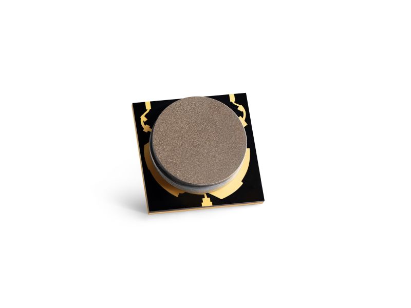
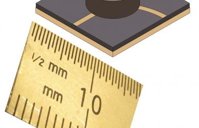
5.1 Microstrip/Stripline (Drop-in)
Planar circulators implement ferrite-loaded junctions inside a compact cavity with transitions to microstrip or stripline. To widen bandwidth, designers use multi-section matching, low-parasitic transitions, careful ground via fences, and magnets that provide uniform bias density. The PCB stack-up (dielectric constant/loss tangent) strongly affects RL flatness at the edges. Thermal pads and copper slugs help keep ferrite properties stable under drive.
- Bandwidth levers: multi-section matches, wider junctions with controlled Q, reduced parasitics, magnetic field uniformity.
- Watchouts: IL ripple at the edges, isolation droop with temperature, solder joint stress changing bias gaps over life.
5.2 Coaxial
Coaxial circulators embed a ferrite junction with coax center conductors. Matching can be implemented with broadband reactive elements and resistive damping where acceptable. Connector choice (SMA, 2.92 mm, 2.4 mm, etc.) sets the top-end frequency and practical VSWR. Coaxial designs are popular when you want a replaceable part, flexible cable runs, and decent power handling.
- Bandwidth levers: connector class, transition symmetry, multi-octave matching networks, ferrite with wide gyromagnetic response.
- Watchouts: connector repeatability, PIM in high-power multi-carrier systems, mechanical shock/vibration effects on bias.
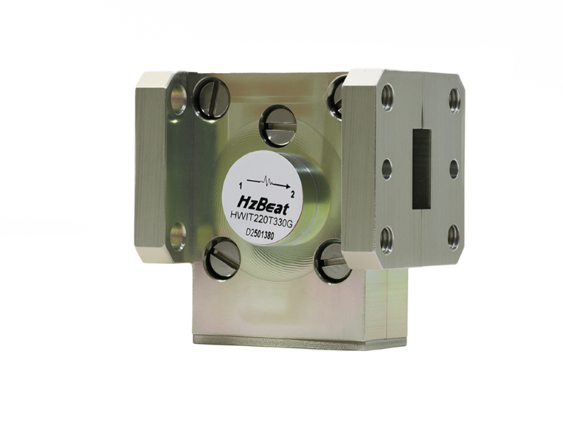
5.3 Waveguide
Waveguide circulators exploit ferrite posts/disks in a waveguide junction. Within a designated waveguide band (e.g., WR-28 for 26.5–40 GHz), they deliver superb IL and ISO, with strong power and thermal margins. Bandwidth can be quite generous as a fraction of the band, but you won’t use the same physical part for 1 GHz and 40 GHz—form factors fundamentally differ with wavelength.
- Bandwidth levers: junction shape, ferrite placement, precision flanges, surface finishes, robust magnet circuits.
- Watchouts: weight, volume, mechanical alignment, and flange flatness; environmental sealing for fielded radar.
6) Selection Guide & Practical Checklists
Use these quick “first-cut” heuristics, then refine with S-parameter data:
6.1 If your priority is “widest overall coverage across many product bands”
- Favor coaxial or planar families—vendors can offer parts from VHF/UHF through C-/X-/Ku-/Ka-band and beyond.
- Ask for IL/ISO vs. frequency plots over temperature; verify VSWR at the band edges where broadband designs struggle.
6.2 If your priority is “best in-band IL + ISO at high power”
- Favor waveguide or high-power coaxial parts; expect larger size and cost, but excellent electrical margins.
- Confirm power handling under your modulation (crest factor, duty cycle) and your ambient/altitude scenario.
6.3 Engineering Checklist
- Bandwidth target: center frequency, fractional bandwidth, and passband ripple limits.
- IL/ISO/RL: minimums across temperature and tolerance; check mismatch protection for the PA.
- Power/Thermal: PEP vs. average power, heatsinking options, ferrite Curie margin, magnet stability.
- Packaging: PCB stack-up for drop-ins, connector class for coax, waveguide size/flange type for WG.
- Reliability: shock/vibration, humidity, salt-fog (for coastal installs), and lifecycle drift.
7) FAQs
Q1. Is “wider bandwidth” always better?
No. Wider bands typically increase IL ripple, strain isolation, and complicate matching. If your radio uses a narrow operating block, a tighter-band part with better IL/ISO can outperform a broadband option.
Q2. Can a single circulator cover 600 MHz and 28 GHz?
Not as a single physical part. You can source families spanning those ranges (especially coaxial and planar lines), but each unit is designed for a defined band.
Q3. Why do waveguide parts look “narrow” on datasheets yet get praise for bandwidth?
Datasheets reference a specific waveguide band. Within that band, waveguide often offers generous fractional bandwidth and superior IL/ISO versus other types.
Q4. Any tips for pushing planar bandwidth?
Use low-loss laminates, tight ground via fences, minimize launch parasitics, and co-optimize magnet circuit uniformity with multi-section matching networks.
8) References & Further Reading
- D. M. Pozar, Microwave Engineering, 4th ed. (textbook overview of non-reciprocal ferrite components).
- Microwaves101 Encyclopedia — Practical notes on ferrite circulators and isolators.
- General vendor application notes on ferrite junction design, matching, and thermal considerations.
Relateds


About the Author

HzBeat Editorial Content Team
Marketing Director, Chengdu Hertz Electronic Technology Co., Ltd. (Hzbeat)
Keith has over 18 years in the RF components industry, focusing on the intersection of technology, healthcare applications, and global market trends.