Microwave Circulators Explained: Principles, Design, and Applications
Updated on:
Keywords: microwave circulator, RF circulator, non-reciprocal device, ferrite circulator, Ku-band, Ka-band, VSWR, S-parameters
A tech‑media style deep dive for RF engineers and buyers — covering microwave circulator physics, S‑parameters, RF circulator types, design/production/testing, applications, and future trends.
Explore Microstrip Circulators · See Drop‑in Series · Coaxial Lineup · Waveguide Solutions
Introduction
Microwave circulators — often simply called RF circulators — route energy directionally (1→2→3→1) to provide signal isolation, enable antenna sharing for TX/RX, and protect LNAs/PAs from mismatch. From sub‑6 GHz base stations to Ku/Ka‑band SATCOM and mmWave imaging, circulators keep links stable and measurement benches safe.
Choosing between microstrip/stripline, drop‑in, coaxial, and waveguide formats means balancing integration, bandwidth, power handling, and thermal behavior. Publishing S‑parameter files and three‑temperature data accelerates design‑in for engineering customers.
Principles & Physics
Circulators are non‑reciprocal devices realized by magnetized ferrites under a DC bias field (B0). The effective permeability becomes a tensor (per the Polder model), and magnetic dipoles undergo Larmor precession. Forward and reverse waves see different propagation constants, so power is steered directionally with low insertion loss and high isolation. Classic analyses show how ferrite resonance, bias level, and junction symmetry set the op...
Three‑port Y‑junctions and four‑port topologies are common. Disc radius/thickness, conductor angles, and substrate permittivity (εr) define center frequency and bandwidth; magnetic saturation and temperature drift constrain operating margins. For chip‑scale research, time‑varying or active networks can emulate non‑reciprocity, trading off linearity and power capability.
Design tip:
Bias near but below saturation to maintain isolation over temperature; verify with hysteresis sweeps.
S‑Parameters & Figures of Merit
Circulators are described by a 3×3 S‑matrix. Around center frequency, one forward path exhibits low loss (≈0.3–1.0 dB typical), while the reverse path is highly attenuated (isolation ≥20–25 dB; higher for radar). Good return loss/VSWR keeps reflections minimal. Bandwidth is often specified as a percentage of the center frequency. Average/peak power ratings must reflect duty cycle and mismatch survival.
[S] ≈ ⎡ S11 S12 S13 ⎤ low‑loss: |S12|, |S23|, |S31|; isolation: |S13|, |S21|, |S32| ⎢ S21 S22 S23 ⎥ return loss/VSWR at all ports; verify across temperature and power ⎣ S31 S32 S33 ⎦
Wideband hint:
Multi‑section matching and absorptive loading can flatten isolation over broader bands (with size/loss trade‑offs).
Metrology:
Use TRL/SOLT calibration with proper de‑embedding; publish Touchstone files for customers.
Types & Form Factors
Waveguide Circulator
Targeting Ku/Ka/mmWave, the waveguide circulator is preferred for high power, high isolation, and robust thermal behavior in SATCOM and radar payloads. Trade‑offs: size/weight and integration complexity.
Coaxial Circulator
Coaxial circulators deliver very low insertion loss and strong power handling with standardized connectors (N, SMA, 2.92 mm). They are workhorses in ground stations, protection lines, and measurement benches.
Microstrip / Stripline Circulator
Planar and compact, microstrip/stripline versions integrate on PCB/LTCC for 5G/6G front‑ends and phased‑array T/R modules. Expect lower power and narrower absolute bandwidth vs. larger form factors.
Drop‑in Circulator
Drop‑in devices bridge planar compactness and coaxial robustness. Screw‑mounted into modules, they balance mid‑power handling with low loss — common in radar T/R chains and PA protection.
Selection rule‑of‑thumb:
Microstrip/SMT → compact & low power; Drop‑in → mid‑power radar/PA; Coaxial/Waveguide → high‑power or wideband SATCOM/radar.
Design Considerations
Materials & Bias
Choose ferrite with suitable saturation magnetization (Ms) and linewidth. Set B0 to center the non‑reciprocal response at target frequency with temperature headroom. Housing and magnet layout should ensure field uniformity; avoid partial saturation or fringe‑field coupling into nearby ICs.
Geometry & Matching
Disc radius/thickness, conductor widths/angles, and resonator loading shape the pass path and isolation notches. Use impedance transformers, matching rings, and tapered junctions to broaden bandwidth. For mmWave, machining tolerance and surface roughness dominate excess loss.
EM Simulation & Co‑Design
Combine full‑wave EM (HFSS/CST) with circuit co‑simulation (ADS). Include connector launches (SMA‑to‑microstrip), waveguide transitions, and thermal/mechanical constraints; otherwise lab results can deviate markedly from simulations.
Thermal & Power
Estimate core loss and ΔT under worst‑case mismatch and pulse conditions. Provide heatsinking paths (metal baseplates, airflow) and verify isolation at elevated temperatures. Duty cycle and crest factor matter for ferrite stress.
Manufacturing & Process Control
- Ferrite preparation: cutting, lapping, polishing; verify thickness and flatness.
- Bias assembly: magnet selection/orientation and clamping; ensure field uniformity across the disc.
- Housing & plating: waveguide/coaxial machining, plating for corrosion and RF conductivity.
- Junction alignment: preserve symmetry across ports; minimize gaps and tilt.
- Final test: S‑parameters over temperature, power burn‑in, isolation/VSWR guard‑bands.
Establish SPC on εr, ferrite linewidth, magnet flux, and mechanical tolerances. Record 3‑temperature S‑parameters for each lot.
Test & Characterization
Small‑Signal
Measure with a Vector Network Analyzer using SOLT/TRL calibration. Validate insertion (S12/S23/S31), isolation (S13/S21/S32), and return loss at all ports across band and temperature. Provide Touchstone files in the datasheet bundle.
Large‑Signal & Reliability
- Average/peak power characterization; include pulse width and duty cycle.
- Hot‑box tests and thermal soak; track isolation drift vs. temperature.
- Mismatch survival (e.g., 2:1–3:1 VSWR) at rated power; document failure modes.
System‑Level
Validate with the intended PA/LNA/antenna. Include harmonics and intermodulation checks if the circulator sits near nonlinear stages. For T/R modules, confirm isolation margin under vibration/shock.
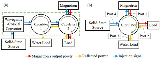
Fig. 1 — Four‑port waveguide circulator in a high‑power injection‑locked system (Open Access, MDPI Electronics).
Applications
Wireless & SATCOM
Circulators enable shared antennas for TX/RX while protecting PAs from reflections. Coaxial and waveguide units dominate ground stations for their ruggedness and power margin.
Radar (Airborne, Naval, Automotive)
Route high‑power pulses to the antenna and weak echoes to the receiver — a dynamic isolation task under thermal and mechanical stress. Waveguide remains the workhorse at higher bands/power.
Measurement & Protection
On benches and production lines, circulators enforce directionality and protect instruments during amplifier/filter evaluations. Choose low‑loss, wideband versions for multi‑band verification chains.
Emerging: Quantum & On‑Chip Non‑Reciprocity
Ferrite‑free approaches (time‑varying capacitors, active transistor networks, acoustic non‑reciprocity) aim at chip‑scale integration. Promising for IoT/edge, but not yet matching ferrite devices in linearity/power.
Future Outlook
- Higher integration via LTCC/SoP with careful shielding and magnetic return paths.
- Wider bandwidth using multi‑mode resonators and advanced ferrites.
- Design automation: AI‑assisted synthesis for non‑reciprocal junctions and tolerance‑aware optimization.
- Ferrite‑free R&D for ultra‑compact IoT/edge; watch isolation/power trade‑offs.
Quick FAQ
Can a circulator replace a duplexer?
Sometimes — for narrow bands with suitable power/linearity margins. Classic duplexers offer sharp channel selectivity; circulators provide directional isolation without steep filtering.
What isolation is “good enough”?
Start at ≥20–25 dB for benign links. For radar/PA protection, engineer margin up to 30–35 dB (or more) depending on mismatch and pulse power.
How to read the datasheet quickly?
Check frequency/bandwidth, insertion loss, isolation, VSWR, power (avg/peak), connectors/footprint, and temperature rating. Ask for S‑parameter files and 3‑temperature data.
Relateds


About the Author

HzBeat Editorial Content Team
Marketing Director, Chengdu Hertz Electronic Technology Co., Ltd. (Hzbeat)
Keith has over 18 years in the RF components industry, focusing on the intersection of technology, healthcare applications, and global market trends.