Next-Gen Ferrite Circulators for Reliable Microwave Systems
Updated on:
Keywords: ferrite circulator, microwave systems, RF circulator, reliability, radar, satellite

Introduction
In high-stakes microwave links, reliability is not a luxury—it is the design constraint. Ferrite circulators, a class of non-reciprocal three-port devices, are the quiet guardians that enforce unidirectional power flow, shunting reflections to a termination and preventing runaway oscillations. As bandwidths widen from sub-GHz to millimeter-wave and architectures densify (phased arrays, compact transceivers, active antennas), next-generation circulators must deliver a more nuanced balance: high isolation without penalizing insertion loss, high power handling without thermal runaway, and stable performance across temperature and time.
The “next-gen” qualifier is not marketing garnish. It reflects advances in ferrite composition, magnet circuits, EM-tuned junction geometries, and packaging—drop-in, coaxial, waveguide, even SMT—that collectively push circulators beyond their traditional trade-offs. The outcome is practical: better link margin, lower error vector magnitude (EVM), gentler thermal budgets, and longer mean time between failures (MTBF).
Why Reliability Matters
Mismatch Protection
Antennas ice over, connectors loosen, radomes detune—real-world VSWR happens. A circulator prevents reflected energy from re-entering the transmitter chain by routing it to a matched load. This protects power amplifiers from voltage/current stress, reduces distortion, and avoids protective foldback events that would otherwise collapse link budget.
Signal Integrity
Feedback paths, especially in compact multi-stage front-ends, can provoke oscillation or intermodulation. High isolation between ports attenuates these unintended couplings. The result is cleaner constellations, improved ACLR/ACPR, and more predictable calibration of multi-channel arrays.
Thermal & Aging Stability
Ferrite permeability and magnet bias drift with temperature and time. Next-gen designs include better heat spreading (CuMo carriers, plated interfaces), tighter magnetic circuit control, and process discipline that limit parameter drift over lifecycle, enabling stable IL/ISO in harsh environments.
Design tip: Always analyze worst-case VSWR with statistical mismatch models. Size the termination for peak dissipation during fault and pulsed conditions.
What’s New in Ferrite Circulator Design
Modern circulators are not just better magnets in old housings; they are co-optimized systems:
- EM‑Tuned Junctions: Y‑junction, stripline, or microstrip nodes are optimized with full-wave simulation to achieve flatter isolation across fractional bandwidth without “cliffs” at edges.
- Broadbanding Networks: Integrated matching stubs and resistive/inductive compensation extend usable range from narrowband (a few %) to wide bands (tens of %), even multi-octave in special topologies.
- Bias Uniformity: Magnet shimming and low-hysteresis steels yield consistent bias across the ferrite disk, reducing mode splitting and ripple.
- Thermal Architecture: Heat paths are explicitly engineered—heatsink interfaces, copper-moly carriers, high-κ pads—to avoid hotspots that would lift IL and depress isolation.
- Footprint Miniaturization: Drop-in and SMT packages minimize loop area and parasitics, crucial in dense RF modules and phased arrays.
Key Performance Indicators
Circulator performance is not a single number; it is a vector of trade-offs. The essentials:
- Frequency Range & Bandwidth: Specify center frequency and fractional bandwidth. L/S/C/X/Ku/Ka bands demand different junction scales and bias levels.
- Insertion Loss (IL): Lower IL preserves EIRP and link margin while reducing self-heating. Practical targets in many bands are
≤ 0.2–0.6 dBdepending on geometry and power. - Isolation (ISO): High ISO (
≥ 20–30 dBtypical) suppresses feedback. Beware of band-edge roll-off—verify across temperature and tolerance stacks. - Return Loss (RL): Good port match (
≥ 14–18 dB) avoids re-reflections and eases integration with filters and amplifiers. - Power Handling: Both CW and peak ratings matter; de-rate for duty cycle, ambient, altitude, and enclosure effects.
- Temperature Stability: Characterize across the full operating range; magnet bias and ferrite properties shift with T.
A useful shorthand is to watch the S‑parameters: IL ≈ -10·log10(|S21|^2), ISO ≈ -10·log10(|S31|^2). But never reduce qualification to one point—sweep frequency, temperature, and mismatch.
Ferrite Materials & Magnetic Bias
Ferrite is the circulator’s heart. Material composition determines saturation magnetization, linewidth, and loss tangent. Process control (grain size, porosity, sintering atmosphere) tunes permeability and Q. In parallel, the magnet circuit sets the operating bias point—too low and isolation collapses; too high and IL rises or stability suffers.
Material Engineering
- Reduced Loss: Doped ferrites and refined microstructures push down dielectric and magnetic loss.
- Thermal Coefficients: Tailored curves limit drift across wide temperature swings.
- Supply Chain Resilience: Alternatives to rare-earth-heavy mixes reduce sensitivity to materials volatility.
Bias Field Design
Magnet topology (ring vs. blocks), pole-piece geometry, and shimming control bias uniformity. Leakage fields must be considered when co-locating sensitive LNAs, oscillators, or MEMS. In compact modules, pay attention to installation orientation and nearby ferromagnetic parts that detune bias.
Applications
- Radar: As T/R duplexers, circulators protect PAs during pulse compression and maintain receiver linearity under high reflected power.
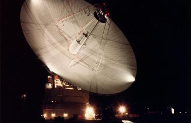
- Satellite & Ground Terminals: In BUC/LNB chains, circulators isolate stages and safeguard against load transients—especially in transportable VSATs.
- 5G/6G Infrastructure: Massive MIMO radios benefit from compact, low-IL parts that tame coupling in dense arrays.
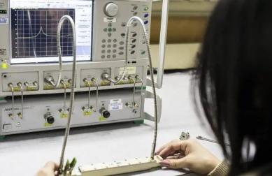
- Test & Measurement: VNA‑based fixtures and automated benches rely on predictable isolation to stabilize measurements.
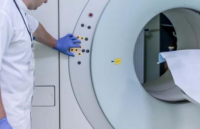
- Medical & Industrial: MRI RF chains and ISM heating rigs depend on matched, robust non‑reciprocal elements.
Selection & Integration Guide
The shortest route to a robust design is disciplined selection and integration. Start with bands, environment, and power profile; end with real hardware correlation.
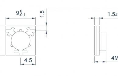
Typical Options by Package
| Package | Band Examples | Typical IL | Typical ISO | Power | Notes |
|---|---|---|---|---|---|
| Drop‑in | L/S/C/X | 0.2–0.6 dB | 20–28 dB | 10–100 W CW | Compact; ideal for modules and arrays |
| Coaxial | VHF–Ku | 0.3–0.8 dB | 20–30 dB | 5–200 W CW | Easy cabling; lab & field friendly |
| Waveguide | X/Ku/Ka | 0.1–0.4 dB | 25–35 dB | High power | Lowest loss at mmWave; mechanical alignment critical |
| SMT/Microstrip | L/S/C | 0.3–0.7 dB | 18–25 dB | Low–mid | Ultra‑compact; watch PCB stack‑up and bias stray fields |
Integration Checklist
- Define Margins: Frequency, temperature, altitude, duty cycle. Include growth headroom.
- Optimize IL vs. ISO: Do not chase one at the other’s expense; simulate and measure at edges.
- Thermal Path: Use high‑κ pads, planarization, and torque‑controlled fasteners.
- Bias Management: Verify leakage fields around LNAs, oscillators, MEMS—add shields if needed.
- Fixture Effects: Connectors, transitions, and enclosure currents skew results—co‑simulate the whole chain.
- EMC/EMI: Consider grounding strategy and current returns; avoid inadvertent loops.
Validation & Qualification
Reliability lives or dies in validation. A minimal but meaningful flow looks like this:
- Room‑temp Parametrics: Full S‑parameter sweep; initial IL/ISO/RL baseline.
- Environmental: Temperature cycling (e.g., –40 °C to +85 °C), humidity, vibration, and shock per relevant profiles (IEC/MIL/DO‑160 derivatives).
- High‑Power Stress: Load‑pull under controlled mismatch across duty cycles; monitor temperature rise and drift.
- Aging/Bias Drift: Long‑soak at elevated temperature; periodic S‑parameter checks to capture magnet and ferrite drift.
Use consistent fixturing and calibration (TRL/SOLT) and maintain a golden unit per band for cross‑lot comparison. Document everything—magnet field, torque, thermal pads, torque sequence—small details move dB.
FAQ
How do ferrite circulators differ from semiconductor circulators?
Ferrite parts exploit magnetic bias to achieve non‑reciprocity and are mature for high power and wide dynamic range. Semiconductor circulators leverage spatio‑temporal modulation or non‑linearities; they promise integration but today often trade power handling and linearity for size.
Can one device serve multiple disjoint bands?
Wideband solutions exist, but performance typically degrades near edges. For mission‑critical links, band‑specific parts deliver more predictable IL/ISO and thermal behavior.
What about operation above 100 GHz?
Waveguide circulators scale into mmWave, but fabrication tolerances, surface finish, and magnet integration become challenging. Expect tighter assembly controls and higher cost per dB of isolation.
How does magnet aging affect isolation?
Bias field can drift slightly over long timescales and temperature exposure. Design margins, material selection, and periodic calibration (where applicable) mitigate isolation creep.
Relateds

About the Author

HzBeat Editorial Content Team
Marketing Director, Chengdu Hertz Electronic Technology Co., Ltd. (Hzbeat)
Keith has over 18 years in the RF components industry, focusing on the intersection of technology, healthcare applications, and global market trends.