HzBeat’s Guide: How to Select Between Microstrip, Drop-In, Coaxial, and Waveguide Circulators
Updated on:
Keywords: how to select circulators type, microstrip circulator, drop-in circulator, coaxial circulator, waveguide circulator, RF circulator supplier, HzBeat
Selecting the right RF circulator type is a systems decision: frequency plan, power envelope, thermal path, volume/weight, and how you physically integrate the part all matter. This guide compares four mainstream topologies—microstrip, drop-in, coaxial, waveguide—and distills practical selection criteria for 5G radios, radar/AESA, satcom payloads, and medical RF systems.
Industry Context & Use Cases
Circulators sit at the intersection of power handling and isolation. In 5G radios and microwave backhaul, designers favor compact PCB-level parts to keep mass and cost in check. In X/Ku/Ka-band radar and satcom, insertion loss budgets and CW/peak power drive many teams to coaxial or waveguide solutions. In MRI and other medical systems, high isolation protects sensitive receive chains during transmit pulses.
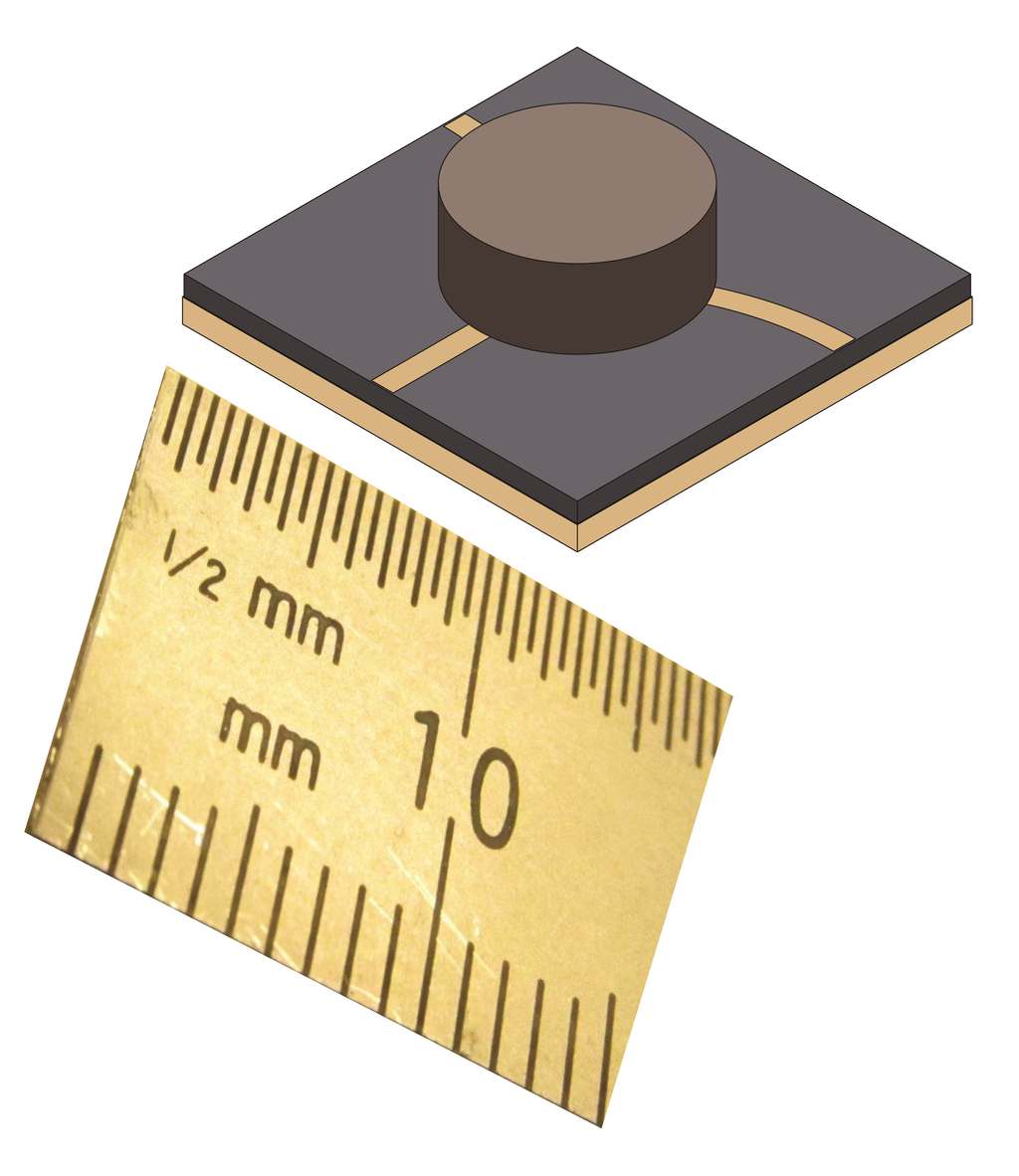
Microstrip junction circulator. Image: Dlinkhart, CC BY-SA 4.0. Source: Wikimedia Commons.
What a Circulator Does (Engineering View)
An RF circulator is a passive, non-reciprocal three-port device. Energy entering port 1 exits port 2; port 2 to port 3; port 3 to port 1. This one-way routing enables duplex operation, protects LNAs from reflected PA energy, and stabilizes complex RF chains. Ferrite biasing (or other non-reciprocal mechanisms) sets the directionality; geometry, ferrite properties, and magnetic circuit define insertion loss (IL), isolation, and VSWR performance. In space or high-reliability environments, designers also evaluate performance drift versus temperature, shock/vibration survivability, and outgassing/radiation behavior.
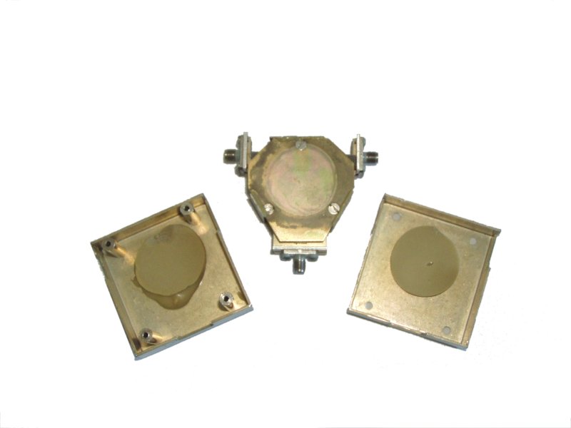
Ferrite circulator (disassembled). Photo: Averse, CC BY-SA 3.0/GFDL. Source: Wikimedia Commons.
Types & Trade-offs
Microstrip Circulators
- Best for PCB-level integration, volume-sensitive 5G modules
- Bands Sub-GHz to mmWave (design dependent)
- Pros Small footprint, light weight, scalable manufacturing
- Consider Lower power headroom; thermal drift vs. coax/waveguide
Microstrip realizations use a planar junction on PCB or ceramic substrates with ferrite tiles and a magnet stack. They are attractive for RU/DU and small cells where density dominates. Watch thermal paths and ground integrity near the junction; temperature rise can degrade isolation and shift center frequency. For multi-band radios, ensure adequate margin for filter+PA mismatch dynamics.
Explore: HzBeat Microstrip Circulators
Drop-In Circulators
- Best for T/R modules and compact subassemblies
- Integration Screw-mount with gasket/pad; precise torque & coplanarity
- Pros Good isolation in small volume; reliable assembly-line flow
- Consider Thermal stack-up; keep-out for fasteners and RF vias
Drop-ins balance PCB-level integration and RF performance. In AESA tiles, they frequently sit between PA, antenna port, and limiter/LNA. Pay attention to heatsinking under the baseplate and to screw torque: both affect return loss and isolation stability over temperature.
Explore: HzBeat Drop-In Circulators
Coaxial Circulators
- Best for Medium–high power chains with coax I/O
- Pros Robust power handling; simple cabling & quick swaps
- Consider Larger and heavier than microstrip/drop-in
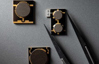
Assorted drop-in/coaxial junction circulators. Image: Uiy-tech, CC BY-SA 3.0. Source: Wikimedia Commons.
Coaxial packages cover wide bands from VHF/UHF to Ku/Ka with meaningful CW and peak power. They’re preferred in test stands, fielded radios with coax harnessing, and as protection elements near external connectors. Ensure the connector class (SMA, N, 7/16 DIN, TNC, etc.) meets voltage-stand-off and thermal cycling requirements.
Explore: HzBeat Coaxial Circulators
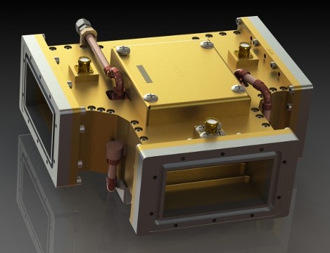
Waveguide Circulators
- Best for High-power, low-loss microwave/mmWave chains
- Pros Excellent IL/QL at power; stable over environment
- Consider Envelope & weight; mechanical alignment; cooling
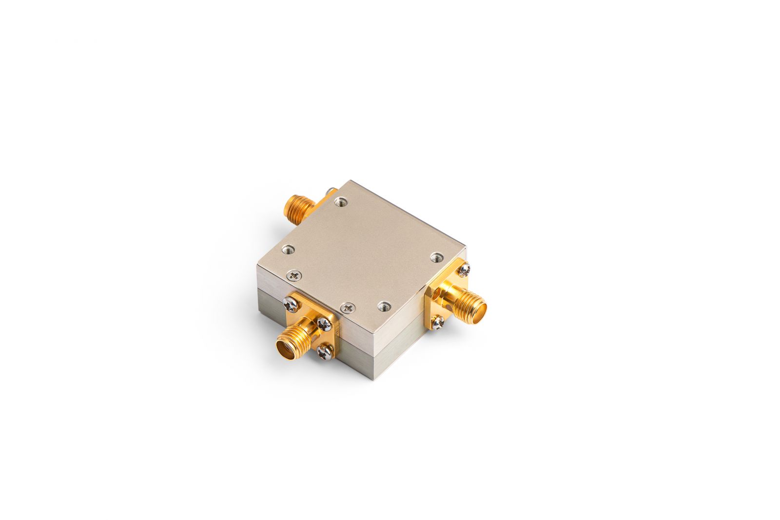
Coaxial circulators. Image: Uiy-tech, CC BY-SA 3.0. Source: Wikimedia Commons.
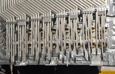
Waveguide devices dominate when dissipation and voltage-breakdown limits push beyond coax or planar parts—e.g., X/Ku/Ka radars, high-throughput satellite payloads, and RF accelerators. Designers sometimes add liquid cooling channels or heat exchangers near the ferrite puck to sustain duty cycles.
Explore: HzBeat Waveguide Circulators
Spec Comparison Table (Typical Ranges)
These are indicative engineering ranges to frame trade-offs. Final performance depends on band, matching, thermal design, and part configuration.
| Type | Frequency Coverage | Insertion Loss (IL) | Isolation | VSWR | Power Handling | Physical / Integration |
|---|---|---|---|---|---|---|
| Microstrip | ~0.5–40+ GHz (design-dependent) | ~0.4–1.2 dB | ~18–25 dB | ≤1.5–1.8 | Low–medium | PCB-level; smallest footprint |
| Drop-In | ~0.5–50 GHz | ~0.3–0.8 dB | ~20–28 dB | ≤1.4–1.7 | Low–medium (better than microstrip) | Screw-mount; module-friendly |
| Coaxial | ~20 MHz–40+ GHz | ~0.25–0.7 dB | ~20–30 dB | ≤1.25–1.6 | Medium–high (CW/peak) | Connectorized; quick swaps |
| Waveguide | ~2–200 GHz (by WG band) | ~0.1–0.4 dB | ~22–35 dB | ≤1.2–1.5 | High / liquid-cooled options | Flanged; highest envelope |
Selection Checklist
- Operating band & bandwidth: L/S/C/X/Ku/Ka/WR series. Keep margin for filter PA mismatch and detuning with temperature.
- Power & duty cycle: CW, peak, VSWR under mismatch. Derate for altitude/vacuum and thermal rise.
- Thermal & mechanical: Baseplate impedance, heatsink interface, torque spec, CTE stack-up.
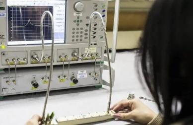
- EM spec targets: IL, isolation, return loss/VSWR, and repeatability across temperature and vibration.
- Integration path: PCB (microstrip), module (drop-in), harness (coax), or flanged assemblies (waveguide).
- Reliability & environment: Shock/vibe, thermal cycles, humidity/condensation; vacuum/radiation for space.
- Compliance & supply: ITAR/EAR, RoHS/REACH, in-line QA, FAI, lot traceability.
HzBeat application support.
Share your target band, power, VSWR, size limit, and environment, and our team will propose a topology and preliminary spec window with lead time and MOQ.
Application Patterns
5G & Wireless Infrastructure
RUs and small cells bias toward microstrip or drop-in to hit cost/size targets. Keep an eye on duplexer/PA interaction and thermal rise in dense radio stacks. For outdoor RUs, specify salt-fog and temperature cycling tests.
Radar (AESA/PESA) & EW
High average/peak power and low IL point to coaxial or waveguide. In T/R modules, drop-ins can be used where envelope allows. Validate isolation under temperature and vibration; TRMs impose cycling and load-pull dynamics.
Satellite Communications
Waveguide and high-reliability drop-ins are common in X/Ku/Ka payloads. Pay special attention to multipaction, corona, and vacuum thermal paths. Many designs co-optimize with OMTs, filters, and HPAs on shared heat spreaders.
Medical (MRI) & Industrial
Coaxial circulators with high isolation protect receive chains during transmit. EMC and sterilization requirements may dictate enclosure finish and connector selection.
Technology Outlook
Design automation and advanced ferrites continue to expand performance windows—higher Curie temperatures, lower loss tangents, and better bias stability. In waveguide junctions, liquid-cooled or dielectrically loaded structures are used to sustain duty cycle at Ka-band. On the planar side, compact microstrip circulators are being ruggedized for temperature cycling and shock without large drift, making them increasingly viable in airborne and NewSpace platforms.
FAQ
Q1: Which topology is best for a high-power X/Ku radar chain?
A: Waveguide if the envelope allows; otherwise high-power coaxial with careful heatsinking and connector selection.
Q2: When do microstrip/drop-ins suffice?
A: In compact radios and TR modules with modest power and strict size/cost constraints; validate temperature drift and isolation under mismatch.
Q3: Can microstrip work in space?
A: Yes in certain modules, but many payloads still favor waveguide/drop-in for IL, breakdown margin, and thermal robustness.
References
- IEEE Transactions on Microwave Theory and Techniques – components & system-level research.
- NASA NTRS – historical and design studies on waveguide/microstrip circulators, duplexers, and cooling concepts.
- Microwave textbooks and manufacturer notes on ferrite biasing, IL/isolation trade-offs, and TR module integration.
Relateds

About the Author

HzBeat Editorial Content Team
Marketing Director, Chengdu Hertz Electronic Technology Co., Ltd. (Hzbeat)
Keith has over 18 years in the RF components industry, focusing on the intersection of technology, healthcare applications, and global market trends.