C-Band Circulator Supplier Guide: Specs, Power, Size, and Cost
Updated on:
Keywords: C-band circulator,C-band RF circulator,C-band circulator supplier,RF circulator manufacturer,C-band radar,C-band satcom
C-band circulators sit quietly between your PA, antenna, and receiver – but they often decide whether a radar, VSAT hub, or telemetry link stays rock-solid in real weather and crowded spectrum. This guide walks through how to read the data sheet, how to talk to suppliers, and how to balance power, size, and cost for real C-band projects.
1. Why C-Band Circulators Still Matter in Modern Systems
C-band (roughly 4–8 GHz) remains one of the workhorse ranges in microwave engineering. It is heavily used in satellite communications, long-range telemetry, weather radar, air-traffic surveillance, and some 5 GHz wireless systems because it balances path loss, atmospheric absorption, and available device technology. In many of these architectures, C-band ferrite circulators and isolators are the non-reciprocal “traffic circles” that keep forward power moving in the right direction and reflected power safely dumped into a load.
In a typical transceiver chain, a C-band circulator:
- Routes power from the PA towards the antenna with minimal insertion loss.
- Protects the PA by routing reflected power into a matched termination during VSWR events.
- Enables shared antenna configurations, where Tx and Rx share parts of the RF path.
At system level, a 0.2–0.4 dB mistake in insertion loss, or an over-optimistic power rating, can directly translate to lower EIRP, degraded G/T, or shortened PA lifetime. For this reason, C-band circulators should not be treated as generic catalog parts. Choosing the right supplier – and specifying the device correctly – is a real design decision, not just a purchasing formality.
2. Typical C-Band Applications & System Requirements
Most C-band circulator projects cluster into a few application families, each with different priorities for bandwidth, power, size, and cost:
- Satellite uplink (5.9–6.4 GHz typical): Large hub stations and teleports often use high-power waveguide or coaxial circulators in the kilowatt class, with strong requirements for reliability and continuous operation. Insertion loss directly impacts uplink margin and satellite lease efficiency.
- VSAT terminals and enterprise networks: Here power is moderate, but footprint and cost per terminal matter. Many designs use microstrip C-band circulators or drop-in devices integrated into compact RF modules.
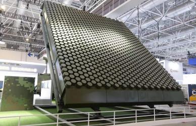
- Weather & surveillance radar: Pulsed kilowatt or tens-of-kilowatt peak power drives rugged waveguide circulators with strict isolation and power handling requirements, often over relatively narrow bands.
- 5 GHz wireless & test equipment: Compact, broadband circulators are used in front ends, T/R modules, and as protection for sensitive measurement receivers.
Across these applications, C-band stands out for its relatively low rain fade and wide coverage, making it a dependable band for large-scale communications infrastructure and radar networks. However, the same band is increasingly crowded, so isolation, intermodulation, and phase stability are more critical than ever when selecting a circulator supplier.
3. Electrical Specifications You Must Get Right
When you scan a C-band circulator data sheet, it is tempting to focus only on “band” and “power”. In practice, at least six groups of parameters must be reviewed carefully to avoid painful surprises during qualification or field deployment.
3.1 Frequency range & bandwidth
First, confirm the operating band under guaranteed specs, not just the center frequency. For example, a C-band satellite uplink circulator might guarantee performance from 5.85–6.425 GHz, while a broadband component could cover 4–8 GHz with relaxed loss and isolation. Ask suppliers to clarify:
- Guaranteed minimum bandwidth versus “typical” bandwidth.
- Performance over full bandwidth and over a narrower “best” band.
- Any separate receive/transmit sub-bands with different specs.
3.2 Insertion loss & return loss
Insertion loss (IL) is often the most important number for link budgets. For high-performance C-band systems, engineers typically target:
- IL ≤ 0.25–0.35 dB for premium hub or radar front ends.
- IL ≤ 0.4–0.5 dB for compact terminal or OEM modules.
Also pay attention to return loss (RL) or VSWR at each port. A very low insertion loss circulator with poor matching can still create unexpected standing waves and degrade PA linearity or efficiency. For serious C-band designs, RL better than 20 dB (VSWR < 1.22:1) is a solid starting point; many radar and gateway projects require 23–24 dB.
3.3 Isolation
Isolation is what separates a reliable non-reciprocal network from a dangerous one. At C-band, you should clearly define:
- Minimum isolation between specified ports (e.g., Port 1→3, Port 2→1, etc.).
- Measurement conditions (CW vs pulsed, power level, temperature, and bandwidth).
- Any derating of isolation at band edges or high power.
For many C-band radar and satcom front ends, 20–23 dB isolation is a minimum; 25–30 dB is preferred when protecting sensitive LNAs and transponders in multi-carrier environments.
3.4 Average, peak, and reflected power
“Power handling” on a catalog line is rarely the full story. A robust C-band supplier will separate:
- Average forward power (CW or duty-cycle-based), limited by heating.
- Peak power (especially in pulsed radar), limited by ferrite saturation and breakdown.
- Reflected power under mismatch, e.g., 50 W average at 1.35:1 VSWR, or 10:1 VSWR for a limited pulse width.
When you compare suppliers, always share your worst-case scenario: maximum transmit power, pulse width and duty cycle (if any), expected antenna VSWR under ice, rain, or mis-pointing, and required lifetime. Ask for clear derating curves versus temperature and VSWR so that reliability engineers can sign off comfortably.
3.5 Temperature range, phase, and stability
C-band systems often see outdoor conditions from −40 °C to +85 °C, or even higher baseplate temperatures in sealed enclosures. Check:
- Guaranteed operating temperature range for all specs.
- Variation of insertion loss and isolation over temperature.
- Phase and group delay variation if the circulator is in a phased-array or coherent radar path.
3.6 Intermodulation, power compression, and reliability
In multi-carrier satellite hubs and broadband ground stations, intermodulation distortion (IMD) and power compression can become the limiting factor. Leading C-band circulator suppliers can characterize:
- IP3 or IMD products when driven with two or more carriers.
- P1dB or effective compression point at C-band.
- MTBF data or accelerated life testing results under realistic power and temperature stress.
4. Package, Size, and Thermal Considerations
C-band circulators exist in several mechanical families. The right choice depends on your integration level and allowable footprint:
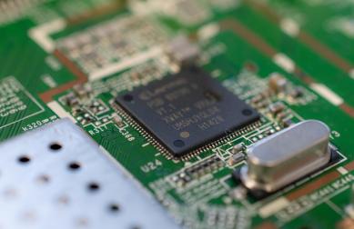
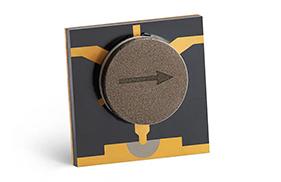
- Microstrip / SMT circulators: Very compact, suitable for high-density RF boards and array tiles. Best when you prioritize size and integration over extreme power handling. See HzBeat microstrip circulators for typical form factors.
- Drop-in C-band circulators: Ferrite devices pushed into a cavity or machined pocket, often with screw-down flanges. Good compromise between footprint, power, and repeatable assembly. Drop-in circulators are widely used in OEM front ends.
- Coaxial and connectorized circulators: Convenient for lab setups, racks, or field-replaceable modules. Slightly larger but easier to rework and swap. Coaxial circulators remain popular in test stations and base stations.
- Waveguide C-band circulators: Highest power handling and lowest loss, at the cost of volume and weight. These often sit in the high-power transmit chain of large radars or teleports; see waveguide circulators for representative examples.
Thermal design is closely tied to package choice. Even a microstrip circulator carrying “only” 20–30 W of average power can run hot if it is mounted on a poorly-cooled board in a sealed outdoor enclosure. When you compare suppliers, ask about:
- Recommended mounting surfaces and torque for good thermal contact.
- Baseplate temperature limits and any required heat-spreader design.
- Available options for integrated heat sinks or higher-temperature ferrites.
5. Cost, Lifetime, and Total Cost of Ownership
C-band circulators vary widely in price, from low-cost catalog SMT devices to custom-engineered waveguide assemblies. Focusing only on unit price is risky; instead, think in terms of total cost of ownership (TCO).
5.1 What really drives the price
- Power class: higher power, larger ferrite volumes, and stricter thermal design all push cost upward.
- Bandwidth: broadband 4–8 GHz circulators are harder to design and tune than narrow 5.8–6.4 GHz devices.
- Package & machining: precision cavity machining, complex waveguide interfaces, and tight alignment tolerances add cost.
- Screening & qualification: devices tested over temperature, power cycling, and vibration (e.g., for aerospace) are naturally more expensive than un-screened commercial parts.
5.2 Looking beyond the unit price
For a fleet of satellite terminals or radar sites, field failure cost can dwarf the initial BOM. A circulator that saves a few dollars but fails early can take a PA, LNA, or even an entire channel offline. When you evaluate C-band suppliers, include:
- Expected failure rate and warranty terms.
- Replacement logistics (lead time, minimum order quantity, last-time-buy strategy).
- Engineering support – how quickly can the vendor help debug anomalies during integration?
The most cost-efficient C-band solution is usually not the cheapest catalog part. It is the device that meets your specs with margin, integrates cleanly in your mechanics, and can be supported throughout the project lifetime without unpleasant surprises.
6. How to Evaluate a C-Band Circulator Supplier
A strong C-band circulator supplier is more than a factory; it is effectively part of your RF design team. When you screen potential partners, look beyond glossy brochures and ask specific questions in five areas:
- Design capability: Do they have in-house ferrite and electromagnetic design expertise, or do they only resell third-party parts? Can they tune designs for your exact band, power, and package?
- Process control: How do they control ferrite batches, magnetization, plating, and assembly tolerances? Can they share Cpk data or process capability for key parameters like IL and isolation?
- Test infrastructure: Do they own calibrated vector network analyzers covering your full C-band, high-power test benches, and thermal chambers? Can they provide s-parameter files and temperature-swept data?
- Customization & support: Can they help with matching network design, layout recommendations for broadband microstrip circulators , or co-design with your PCB stack-up?
- Quality & logistics: What certifications do they hold (e.g., ISO 9001, defense or aerospace qualifications)? Can they support ramp-up, buffer stock, and long-term supply in a volatile RF components market?
Ask each candidate supplier to share at least one application case near your required band and power level, including s-parameter plots and long-term stability data. If a vendor cannot show real examples in C-band, they will likely learn on your project – at your risk.
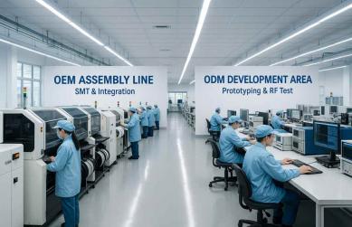
7. Example: Working with HzBeat for C-Band Circulators
HzBeat focuses on RF circulators and isolators from 20 MHz up to 200 GHz, covering microstrip, drop-in, coaxial, waveguide, and SMT packages. For C-band projects, this wide portfolio is useful because many systems blend compact front-ends with high-power stages in the same platform – for example, a microstrip T/R module feeding a higher-power coaxial or waveguide chain.
Typical HzBeat support for C-band customers includes:
- Custom center frequency and bandwidth in the 4–8 GHz range.
- Package selection across microstrip, drop-in, coaxial, and waveguide families.
- Optimization for low insertion loss, high isolation, and stable performance over temperature.
- Co-engineering of matching, layout, and thermal design around the circulator.
If your platform also uses C-band isolators or other non-reciprocal components, it is often efficient to source them from the same supplier. Shared ferrite technology, production lines, and test knowledge help keep performance consistent across variants.
8. How to Write a Clear RFQ & Data Sheet for C-Band Circulator Suppliers
A precise RFQ will save weeks of back-and-forth and avoid misunderstandings that show up during hardware bring-up. At minimum, include the following items when you approach C-band circulator suppliers:
- Target band: center frequency and minimum guaranteed bandwidth (e.g., 4.4–5.0 GHz, 10% fractional bandwidth).
- Required IL, RL, isolation: per port, across the full band, and at temperature extremes.
- Power profile: average and peak power, pulse width and duty cycle, and worst-case antenna VSWR.
- Operating environment: baseplate or case temperature range, altitude, humidity, and any shock/vibration requirements.
- Package preferences: microstrip, drop-in, coaxial, or waveguide, plus maximum footprint and height.
- Production needs: prototype quantities, expected annual volume, and desired design lifetime.
You can also ask suppliers to propose two options: a “performance-optimized” version (lower loss, higher isolation) and a “cost-optimized” version. Seeing the trade-off curve between IL, power, and price often helps internal decision-makers select a realistic spec for C-band hardware.
9. FAQ
- Q1: What is the typical C-band range for circulators?
Most practical C-band circulators are designed anywhere between 4–8 GHz, with common sub-bands such as 4.4–5.0 GHz and 5.85–6.425 GHz for satellite and radar use. The exact tuning is customized to your application. - Q2: When should I choose a waveguide C-band circulator?
Use waveguide when you need very low insertion loss and very high peak or average power, such as large radar transmit chains or high-power teleport uplinks. For compact terminals and modules, microstrip, drop-in, or coaxial packages are often more practical. - Q3: Can one C-band circulator cover both Tx and Rx?
Sometimes yes. A broadband microstrip or drop-in circulator can span both transmit and receive sub-bands if its IL and isolation are acceptable for both paths. In high-performance systems, designers often separate Tx and Rx circulators to optimize each path. - Q4: How do I estimate the thermal margin for my circulator?
Combine datasheet insertion loss and power ratings with your actual forward and reflected power, then compute expected dissipation. Add ambient temperature, enclosure rise, and baseplate thermal resistance to ensure the circulator’s internal ferrite and magnets remain within specified limits under worst-case conditions. - Q5: Can C-band circulators be customized for very narrow bands?
Yes. Narrow-band C-band circulators with optimized IL and isolation can be designed for specific radar or satcom channels. This often improves performance but reduces tuning margin, so long-term band usage and regulatory considerations should be reviewed carefully.
Relateds

About the Author

HzBeat Editorial Content Team
Sara is a Brand Specialist at Hzbeat, focusing on RF & microwave industry communications. She transforms complex technologies into accessible insights, helping global readers understand the value of circulators, isolators, and other key components.