Ku‑Band RF Circulator: Specs, Integration & Reliability
Updated on:
Keywords: ku-band circulator, ku band isolator, RF circulator supplier, RF isolator
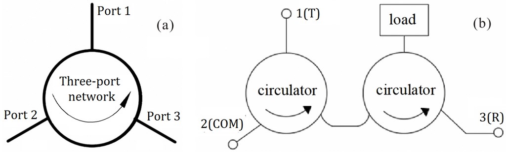
Fig. 1 — Three‑port circulator and cascade "circulator → isolator" schematic (X‑band shown; principles apply to Ku). Source: Tang et al., 2024, Micromachines — CC BY 4.0.
Spanning 12–18 GHz, the Ku‑band anchors satellite broadband (VSAT), in‑flight connectivity, airborne radar and compact gateways. At the heart of many front‑ends sits a Ku‑band circulator — a non‑reciprocal device routing power TX→ANT→RX with minimal insertion loss and high isolation. This report blends the neutrality of a media‑style explainer with the brand authority of HzBeat: we unpack principles, packaging, specs, reliability and applications, then map a forward roadmap — supported by open‑license research figures (CC BY 4.0) and practical integration notes.
Ku‑band 12–18 GHz · IL ≤ 1.0 dB · Isolation ≥ 18–20 dB · VSWR ≤ 1.25:1 · −40…+85 °C
Table of Contents
- Ku‑Band Landscape & Why Circulators Matter
- Principles & Materials — Ferrite and Beyond
- Packaging: Microstrip, Drop‑in, Coaxial, Waveguide
- Specs & Benchmarks (Ku‑Band Targets)
- Integration Playbook for SATCOM & Arrays
- Reliability & Qualification
- Market Trends & HzBeat Positioning
- FAQ
- References & Image Credits
Ku‑Band Landscape & Why Circulators Matter
The Ku‑band circulator or Ku‑band isolator safeguards receivers and stabilizes transmit chains by enforcing one‑way flow. Compared with lower bands, Ku shrinks apertures for mobile platforms; compared with higher mmWave, it tempers rain fade and hardware complexity. Across VSAT, IFC, maritime broadband and airborne radar, every decibel counts — low insertion loss (IL) and robust isolation directly map to link margin, EIRP and G/T budgets.
Principles & Materials — Ferrite and Beyond
Ferrite Y‑junction circulators exploit magnetized ferrite pucks to break reciprocity. In practice, engineers balance three levers: IL vs. isolation, size vs. thermal stability, and cost vs. qualification. Material uniformity, junction symmetry and bias tolerance govern passband flatness and drift over temperature. Emerging research explores non‑magnetic / time‑variant approaches that replace permanent magnets with switched networks and time‑varying phase shifters.
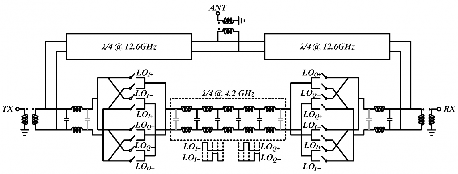
Fig. 2 — Ku‑band non‑magnetic (time‑variant) CMOS passive circulator concept and block diagram. Source: Gao et al., 2023, Micromachines — CC BY 4.0.
These non‑magnetic Ku‑band circulator concepts are not drop‑in replacements for high‑power ferrite devices yet, but the design vocabulary (phase control, symmetry, bias‑free isolation) increasingly informs mainstream Ku developments. For flight hardware, ferrite remains the dominant option due to power handling, linearity and thermal robustness.
Packaging: Microstrip, Drop‑in, Coaxial, Waveguide
No single package wins every Ku scenario — choose by power, volume, assembly and reliability targets:
- Microstrip / SMT Ku‑band circulator — highest density and reflow‑ready, perfect for phased arrays and compact terminals. See HzBeat microstrip circulators and SMT isolators.
- Drop‑in circulator — retrofit‑friendly with predictable grounding/thermals. See drop‑in circulators.
- Coaxial circulator — rugged and broadband; convenient for test sets and high‑power sub‑assemblies. See coaxial circulators.
- Waveguide circulator — lowest loss and peak power handling for uplinks and hot environments. See waveguide isolators.
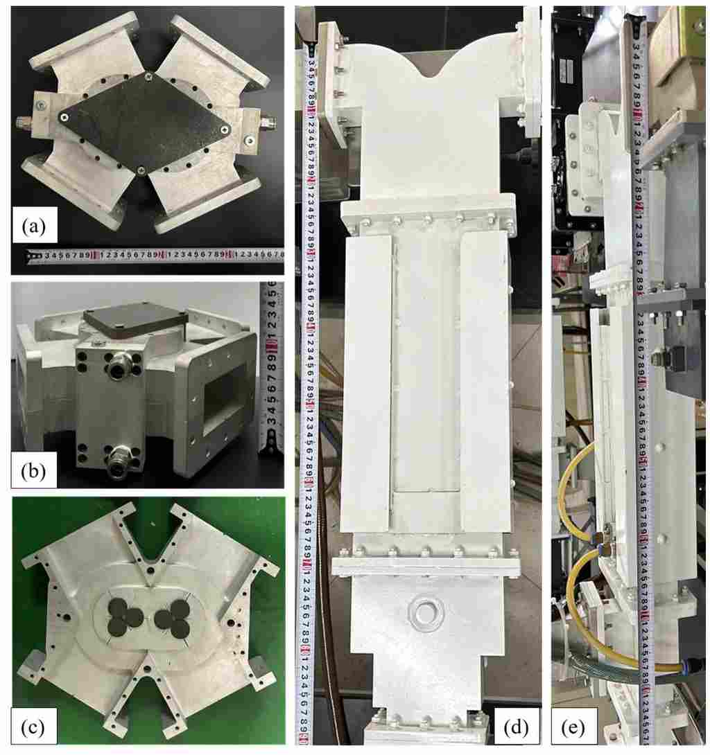
Fig. 3 — Compact four‑port waveguide circulator (exterior and interior) supporting kW‑class power. Source: Mi et al., 2024, Electronics — CC BY 4.0.
Specs & Benchmarks (Ku‑Band Targets)
| Parameter | Ku‑Band Target | Engineering Notes |
|---|---|---|
| Frequency | 12–18 GHz | Custom sub‑bands common (e.g., 13.75–14.5 GHz uplink; 10.7–12.75 GHz receive) |
| Insertion Loss (IL) | ≤ 0.8–1.0 dB | Microstrip/SMT near 1.0 dB; waveguide typically lower |
| Isolation | ≥ 18–20 dB | Higher isolation curbs PA→RX leakage in arrays |
| Return Match | VSWR ≤ 1.25:1 | Maintain flange/gasket integrity for waveguide joints |
| Power (CW) | Up to ~100 W | Thermal path and chassis conduction dominate reliability |
| Operating Temp. | −40…+85 °C | Flight programs extend to TVAC and radiation tests |
Integration Playbook for SATCOM & Arrays
- Grounding & Vias: Stitch grounds densely around the junction; keep RF returns short. For drop‑ins, machine a flat pocket and check coplanarity.
- Thermal Budget: Simulate worst‑case VSWR/duty; give the circulator a low‑θ path to the chassis (graphite pad or solder preform).
- Bias & Drift: Specify ferrite with tight magnetization tolerance; chamber‑sweep S‑parameters across −40/+85 °C.
- EMI/EMC: Bias fields can couple to magnetometers/compasses; define keep‑outs and shielding in avionics.
- Array Effects: Validate mutual coupling and edge bias shifts across tiles; verify array‑level calibration.
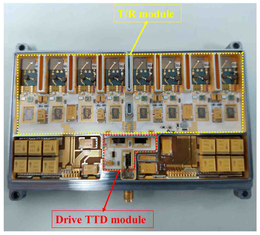
Fig. 4 — LTCC‑based Ku‑band 8‑channel T/R module photograph (module includes ferrite circulators). Source: Liu et al., 2022, Sensors — CC BY 4.0.
Reliability & Qualification
For flight‑class Ku‑band circulator hardware, reliability is a specification: random vibration, sine sweep, thermal cycling, thermal vacuum (TVAC) and program‑specific radiation exposure are commonplace. Common field failures include thermal overstress under mismatch, flange leakage in waveguide joints, and bias drift in poorly controlled ferrites. Controls include torque specs for flanges, gasket inspection, and IL/ISO trend logs over temperature and power.
Market Trends & HzBeat Positioning
Three shifts shape the Ku roadmap: (i) miniaturization for terminals and arrays (SMT/LTCC), (ii) higher power density in uplinks and gateways (waveguide/coax with improved thermals), and (iii) materials/process innovation to reduce drift and de‑risk supply. HzBeat aligns with this trajectory through ferrite material control, precision lapping/alignment and SPC‑driven manufacturing — offering microstrip circulators, drop‑in circulators, coaxial circulators and waveguide isolators for Ku systems.
FAQ
Q1: Circulator vs. Isolator?
An isolator is a circulator with one port internally terminated to absorb reverse power. Choose isolators when local absorption is preferred over routing.
Q2: Can a circulator replace a duplexer?
Not generally. Duplexers frequency‑separate TX/RX; a circulator provides frequency‑flat non‑reciprocal routing.
Q3: Do you offer Ku‑band customization?
Yes — center frequency, bandwidth, power rating and footprints can be tailored for SATCOM and radar modules. Contact: hzbeat.com/contact.
References & Image Credits
- Tang, X. et al. “Design of X‑Band Circulator and Isolator for High‑Peak‑Power Applications,” Micromachines, 2024. CC BY 4.0. Figure used: g001.
- Gao, J. et al. “Analysis and Design of a Non‑Magnetic Bulk CMOS Passive Circulator at Ku‑Band,” Micromachines, 2023. CC BY 4.0. Figure used: g007.
- Mi, Z. et al. “Compact Four‑Port Waveguide Circulator Using Discrete Ferrites,” Electronics, 2024. CC BY 4.0. Figure used: g008.
- Liu, X. et al. “A LTCC‑Based Ku‑Band 8‑Channel T/R Module…,” Sensors, 2022. CC BY 4.0. Figure used: g003.
Relateds

About the Author

HzBeat Editorial Content Team
Marketing Director, Chengdu Hertz Electronic Technology Co., Ltd. (Hzbeat)
Keith has over 18 years in the RF components industry, focusing on the intersection of technology, healthcare applications, and global market trends.