Can a Circulator Be Used as an Isolator
Can a circulator be used as an isolator? This article explains how a three-port RF circulator can function as a two-port isolator when properly terminated, with conditions, limitations, and application examples.
In RF and microwave engineering, circulators and isolators appear side by side in almost every catalog and block diagram. One of the most common questions from system designers is simple: can a circulator be used as an isolator?
The short answer is yes. A three-port circulator can function as a two-port isolator when one port is properly terminated in a matched load. In fact, many practical microwave isolators are physically built from a ferrite circulator core with an integrated termination. However, whether this is a good idea in a given system depends on several technical details: matching quality, power dissipation, bandwidth, and required isolation.
1. Short Answer
A three-port circulator routes energy sequentially from Port 1 → Port 2, Port 2 → Port 3, and Port 3 → Port 1. If one of these ports is permanently terminated in a matched load, the remaining two ports behave as a two-port isolator: power flows freely in one direction but is strongly attenuated in the reverse direction.
2. How a Three-Port Circulator Works
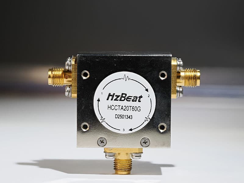
A ferrite junction circulator is a non-reciprocal three-port device, typically implemented as a Y-junction of transmission lines coupled to a magnetically biased ferrite disc. The bias field and ferrite properties create a rotational propagation mode that forces power entering one port to exit from the next port in sequence.
In an ideal three-port circulator, the scattering matrix is often written as:
S = | 0  0  1 |
    | 1  0  0 |
    | 0  1  0 |
This means:
- Power into Port 1 comes out at Port 2.
- Power into Port 2 comes out at Port 3.
- Power into Port 3 comes out at Port 1.
Real devices exhibit finite insertion loss, non-zero reflections, and limited isolation, but the one-way circulation concept still holds and is the foundation for building isolators, duplexers, and protection networks.
3. Turning a Circulator into an Isolator
A two-port microwave isolator is designed to let power flow from Port 1 to Port 2 with low insertion loss, while strongly attenuating power that attempts to travel from Port 2 back toward Port 1.
If we start from a three-port circulator and terminate one port in a matched load, the structure becomes a terminated circulator:
- Use Port 1 as the input.
- Use Port 2 as the output.
- Terminate Port 3 with a high-quality 50 Ω or system-impedance load.
Forward power entering Port 1 flows to Port 2 with low insertion loss. Any power reflected from the load or downstream network at Port 2 circulates into Port 3 and is dissipated in the termination, rather than returning to Port 1. Functionally, the device behaves as an isolator between Port 1 and Port 2.

Many textbooks and manufacturer application notes explicitly define an isolator in this way: as a circulator with one port terminated in a matched load, typically an internal high-power resistor or load assembly.
4. Conditions for Using a Circulator as an Isolator
While the topology is conceptually simple, several practical conditions must be satisfied before a generic circulator can serve as a reliable isolator in a real RF or microwave system.
4.1 High-Quality Matched Termination
The isolation you achieve is limited by the return loss of both the termination and the circulator port. A poorly matched load will reflect some energy back into the junction, reducing effective isolation and potentially creating standing waves. High-performance isolators therefore integrate carefully designed terminations with excellent VSWR and adequate power handling.
4.2 Power Dissipation in the Load
In isolator mode, any reverse power is absorbed in the termination. This includes:
- Reflections from VSWR on the output line or antenna,
- Interfering signals entering from the output side,
- Any mismatch energy during switching or tuning transients.
The load must be sized for the expected worst-case reverse power, including appropriate derating for temperature, duty cycle, and ambient conditions. Underestimating this can result in burned loads or drift in isolation performance.
4.3 Bandwidth and Frequency Alignment
Circulators are designed for specific frequency bands. Using a circulator outside its intended band, even with a perfect load, will degrade both insertion loss and isolation. For broadband systems, a circulator must be selected or designed with sufficient bandwidth to maintain the desired isolation across the full operating range.
4.4 Required Isolation Level
Some applications require only modest isolation (for example, 18–20 dB) to protect a transmitter from antenna mismatch, while others may demand 30–40 dB or more. In a terminated circulator, isolation is determined not only by the intrinsic circulator design but also by how well the load and ports are matched. If very high isolation is required, a purpose-built isolator with optimized termination and multi-stage design may be preferred.
5. Pros and Cons vs. Dedicated Isolators
Using a circulator as an isolator can be attractive in some scenarios, but it is not always the best engineering choice.
5.1 Advantages of Using a Circulator as an Isolator
- Flexibility: A single circulator can be wired as a circulator, an isolator, or part of a duplexer, depending on how it is terminated and connected.
- Inventory simplification: In some labs or low-volume systems, stocking one circulator core and adding external terminations can simplify logistics.
- Reconfigurability: Test setups and configurable platforms can repurpose the same circulator for different roles.
5.2 Advantages of Dedicated Isolators
- Optimized isolation: The internal load, junction, and housing are tuned together to achieve guaranteed isolation performance.
- Thermal management: Dedicated isolators are designed to handle and dissipate worst-case reverse power safely.
- Simpler integration: They are delivered as true two-port devices with specified S-parameters, making system modeling and layout easier.
- Reduced risk: Less dependence on external terminations and assembly quality reduces variability in the field.
6. Typical Application Scenarios
Both circulators and isolators are widely used in modern RF and microwave systems. When a circulator is configured as an isolator, the most common goals are to protect sensitive circuitry and to improve system stability.
6.1 Transmitter Protection
Power amplifiers in radar, SatCom, broadcast, and communication systems can be damaged or become unstable if exposed to large reflected power from mismatched antennas or loads. A circulator-based isolator placed at the PA output routes reverse power into the termination instead of back into the amplifier, enhancing robustness and linearity.
6.2 Shared-Antenna Duplexing
Circulators are often used as duplexers to allow a transmitter and receiver to share a single antenna. In many of these configurations, one or more ports are terminated to control reflections and create effective isolation between the transmit and receive paths.
6.3 Measurement and Test Systems
Vector network analyzer setups, power meter lines, and high-sensitivity receivers often include isolators to prevent reflections from distorting measurements. In some lab environments, engineers will temporarily configure a spare circulator with an external load to serve as an isolator in a test line.

7. FAQ from Practicing Engineers
Q1. Is any circulator automatically a good isolator if I terminate one port?
Not necessarily. While the topology will behave like an isolator, the isolation performance depends on how well the ports and termination are matched, as well as the intrinsic design of the circulator. A generic circulator with mediocre return loss may provide only modest isolation when terminated.
Q2. Can I use a circulator as an isolator at frequencies outside its datasheet band?
This is not recommended. Outside the specified operating band, the circulator’s S-parameters degrade: insertion loss rises, isolation drops, and matching worsens. Using a circulator as an isolator under those conditions can give a false sense of protection while still allowing damaging reflections.
Q3. How do I choose the right load when converting a circulator to an isolator?
Look for a termination with:
- VSWR as close to 1.00:1 as practical over your band of interest,
- Average and peak power ratings above the worst-case expected reverse power,
- Mechanical and thermal compatibility with your housing and cooling scheme.
Q4. If I only need 15–18 dB isolation, is a circulator-based solution acceptable?
In many low- to medium-power systems, yes. If your link budget and device ratings tolerate that level of reverse isolation, and you use a high-quality load, a circulator-based isolator can be an efficient and flexible solution. For precision measurement or critical transmit chains, higher guaranteed isolation is often preferred.
8. About HzBeat – RF Circulator & Isolator Supplier (20 MHz–200 GHz)
HzBeat (Chengdu Hertz Electronic Technology Co., Ltd.) is a specialized RF and microwave component manufacturer focused on high-performance ferrite circulators and isolators from 20 MHz up to 200 GHz. Our portfolio covers microstrip, drop-in, coaxial, waveguide and broadband solutions for radar, SatCom, 5G/6G, test & measurement, industrial and scientific systems where low insertion loss and robust isolation are critical.
For engineers considering whether to use a circulator as an isolator, HzBeat offers carefully optimized devices with low loss, high isolation, and stable performance across temperature and power.
- Microstrip Circulators & Isolators: compact PCB-mount solutions for phased-array radar, small cells, and integrated RF front-ends. Learn more: Microstrip Circulator Series.
- Drop-in Circulators: low-profile ferrite junctions designed for modular T/R modules and microwave subsystems, with low insertion loss and high repeatability: Drop-in Circulator Products.
- Coaxial Circulators & Isolators: convenient inline components for base stations, RF distribution networks and test lines: Typical Coaxial Circulators.
- Waveguide Circulators & Isolators: very low insertion loss and high power capability for radar, SatCom, and high-power instrumentation: Waveguide Circulator Series.
HzBeat also supports ODM customization based on your specific frequency band, power level, isolation requirement, mechanical interface, and environmental constraints. Our engineering team can help you determine whether a circulator-based isolator or a dedicated isolator is the best fit for your RF chain.
Contact HzBeat: [email protected] · www.hzbeat.com
9. References
- Wikipedia, Circulator and Isolator (microwave) – description of circulator behaviour and the terminated-circulator isolator concept.
- RF-CI, Operating Principles of Ferrite Circulators and Isolators and application notes on using circulators as isolators and the role of matched terminations.
- Telewave, RF Ferrite Isolator Basics – explanation of how a three-port circulator becomes an isolator when one port is terminated in a matched load.
- SEI Microwave, What Are Microwave Circulators and Isolators? – overview of circulator and isolator operation and common applications in RF systems.
- Wikimedia Commons image resources: Ferritzirkulator1.jpg, Ferritisolator2.jpg, and AisladorG.JPG – circulator and isolator hardware photographs.
Recommended Products


Keith Wong
Marketing Director, Chengdu Hertz Electronic Technology Co., Ltd. (Hzbeat)
Keith has over 18 years in the RF components industry, focusing on the intersection of technology, healthcare applications, and global market trends.