Ferrite Materials in Modern RF Design — A Deep Dive
Updated on:
Keywords: ferrite materials, RF design, microwave, non-reciprocal devices, RF circulator, RF isolator, gyrator, saturation magnetization, Polder tensor, line width, insertion loss, isolation, permeability, bias field, hexaferrite, spinel ferrite, LTCC, millimeter wave, 5G, SATCOM, radar, Ka-band, X-band
Introduction
Ferrite materials are the quiet workhorses inside countless RF and microwave front-ends. From circulators and isolators to phase shifters and tunable filters, ferrites enable non-reciprocity, power handling, and spectral purity that silicon alone still struggles to deliver. This deep dive distills what practicing engineers need to know: the physics, the material parameters that actually move the needle (e.g., saturation magnetization Ms, line width ΔH, relative permeability μr), how biasing and geometry create one-way traffic for RF energy, and how to specify ferrite-based devices for your next design—whether you are building a compact SMD drop-in at L-band or a high-power waveguide unit for X/Ku/Ka-band radar and SATCOM.
1) What Are Ferrites?
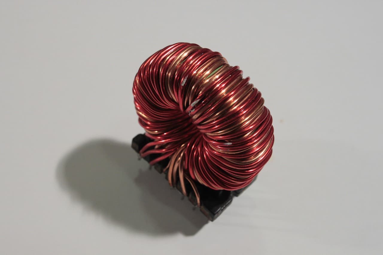
Ferrites are ceramic, iron-oxide-based magnetic materials whose crystal structure and dopants tune their RF-useful permeability tensor and losses. Two families dominate RF: spinel ferrites (e.g., NiZn, MnZn) and hexaferrites (e.g., M-type barium/strontium ferrites). Compared with metallic magnets, ferrites offer high resistivity, suppressing eddy currents at RF/microwave frequencies. They are sintered like ceramics, then lapped and diced to tight tolerances for microstrip, stripline, coaxial, or waveguide geometries.
In non-reciprocal devices, a static magnetic bias aligns the ferrite’s magnetization. Under RF excitation, the magnetization precesses (Larmor precession), producing a gyrotropic permeability tensor (often called the Polder tensor) that breaks time-reversal symmetry. The result: the device allows energy to flow more easily in one direction than the other—exactly what a circulator or isolator exploits.
2) Why Ferrites Enable Non-Reciprocity
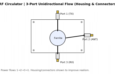
The ferrite’s permeability becomes tensorial in a DC bias field H0. Qualitatively, right- and left-hand circularly polarized components of the RF field see different effective permeabilities (μ+ and μ-). In a circulator, this asymmetry sets up directional coupling so that Port 1 → Port 2 has low insertion loss while Port 2 → Port 1 is diverted to a third port (Port 3). In an isolator, that third port is internally terminated, so reverse energy is dissipated, protecting sensitive PA stages and isolating VSWR.
- Bias-tuned center frequency: The device’s dispersion (and hence center frequency) can be tuned by adjusting H0.
- Broadbanding: Multisection/compound junctions and low-loss materials widen bandwidth while keeping isolation high.
- Power handling: Volumetric ferrite parts spread flux and heat, enabling tens to hundreds of watts in microstrip and kilowatts in waveguide.
3) Key Material & Device Parameters
- Saturation magnetization (Ms): Sets the upper frequency limit and bias needed; higher Ms supports mmWave at reasonable H0.
- Line width (ΔH): Encodes magnetic damping; lower ΔH yields lower insertion loss and better isolation for a given geometry.
- Permeability (μ′, μ″): The real part shapes phase/non-reciprocity; the imaginary part drives loss. Both vary with H0, temperature, and frequency.
- Dielectric constant (εr) & loss tangent: Affect modal impedance and Q, especially in microstrip/stripline junctions.
- Thermal properties: Curie temperature, thermal conductivity, and specific heat determine stability under RF heating.
- Geometry & mode: Junction diameter/thickness, strip widths, and matching networks engineer bandwidth and return loss.
- Packaging & biasing: SMD magnets, integrated pole caps, or external yokes; magnets must be stable vs. shock/temperature.
Device-level specs mirror these levers: insertion loss, isolation, return loss/VSWR, bandwidth, power handling (CW and peak), IP3/linearity, and temperature range. For space/defense, add radiation tolerance, outgassing, and screening.
4) Biasing & Practical Design Considerations
The DC bias field may come from permanent magnets (compact, low-cost) or electromagnets (tunable, heavier). Mechanical tolerances, magnet aging, and temperature drift all perturb H0. Good designs include flux-shaping pole pieces, thermal paths, and (for precision) trim magnets.
- Temperature: IL and ISO shift with temperature—qualify across the full range (e.g., −40 to +85 °C, or wider for aerospace).
- Power & heating: Self-heating moves Ms and ΔH; use copper bases, vias, and heat spreaders.
- Magnet safety: Keep high-grade magnets away from sensitive sensors; design for mechanical shock and ESD handling.
- EMC & EMI: Shield bias fields to avoid detuning nearby LNAs/VCOs; consider closed magnetic circuits.
5) Integration Across Bands & Form Factors
Ferrite devices exist from VHF through W-band. Microstrip/stripline drop-ins suit L/S/C/X-band front-ends and compact radios; coaxial devices bridge moderate power and convenience; waveguide parts cover high power (radar, satcom gateways) into millimeter wave. For SMT, low-profile magnets and LTCC ferrite tapes enable automated assembly.
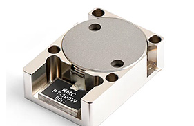
- SMT / SMD: Miniaturized, reflow-capable, careful with magnet thermal limits and nearby ferromagnetic parts.
- Drop-in stripline: Excellent IL/ISO balance with manageable bias; scalable to arrays/T/R modules.
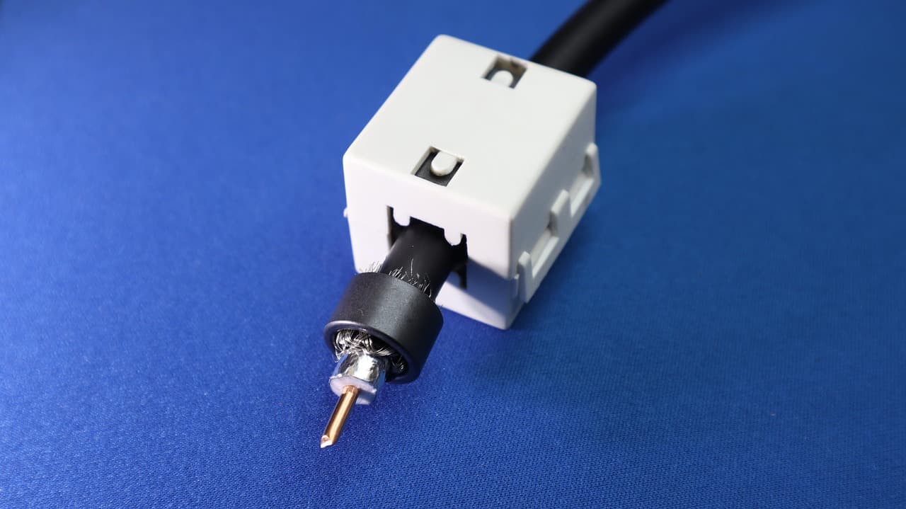
- Coaxial: Rugged, easy to cable; useful for lab, test racks, and moderate-power radios.
- Waveguide: Highest power and Q; precise machining and alignment critical at Ku/Ka-band.
6) Measurement & Modeling
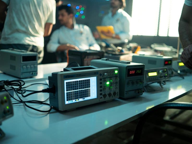
Characterization typically uses VNA S-parameters (S21 IL, S12 reverse loss/iso, S11/S22 match). For material work, extract μ(ω) and ΔH via resonant methods or broadband fixtures. Polder-tensor models feed EM solvers (FEM, MoM) to capture gyrotropy; large-signal thermal models predict power limits. Always cross-check simulation with fixture de-embedding and real bias hardware.
7) Design Trade-offs & Reliability
- IL vs. ISO vs. bandwidth: Improving one often nudges the others—use multi-junction designs and smart matching.
- Size vs. bias: Smaller parts often require stronger magnets or higher Ms materials.
- Thermals vs. linearity: Keep ΔT small to maintain IP3 and frequency stability.
- Manufacturability: Sintering shrink, lapping flatness, and magnet tolerances define Cpk on RF specs.
- Compliance: RoHS/REACH, tin-whiskers in finishes, and magnetic shipping constraints.
8) Emerging Trends & Use Cases
- 5G/6G & small cells: Compact SMT circulators protect PAs and improve coexistence in dense deployments.
- Automotive radar (76–81 GHz): Materials with high Ms and low ΔH push non-reciprocity into mmWave.
- SATCOM & gateways: High-power waveguide isolators stabilize HPAs and protect LNAs in block up/down converters.
- Phased arrays & T/R modules: Drop-in ferrite parts remain a pragmatic path to robust beamforming chains.
- Research: Magnetless non-reciprocity is advancing, but ferrites still dominate for rugged power and bandwidth.
9) Engineer’s Selection Checklist
- Target band & bandwidth; allowable IL and required ISO.
- Power (CW/peak) and thermal path; package style (SMT, drop-in, coaxial, waveguide).
- Bias approach and available space for magnets/yokes.
- Environmental: temperature range, shock/vibe, humidity, radiation (if applicable).
- Manufacturing flow: reflow profile, handling constraints, in-circuit test, and screening.
Summary
Ferrites remain foundational to RF non-reciprocal design because they provide a tunable, power-capable gyrotropic response with manageable loss. By paying attention to material quality (Ms, ΔH), thermal and magnetic design, and the right package for your band and power, you can hit aggressive IL/ISO/VSWR targets from L-band radios to Ka-band gateways—today and for the foreseeable future.
FAQ
Q1. What’s the difference between spinel and hexaferrite for RF?
Spinels are common in lower-GHz microstrip/stripline parts thanks to processability and losses; hexaferrites offer higher Ms useful toward mmWave with appropriate bias.
Q2. How does temperature affect isolation?
Temperature shifts Ms, ΔH, and magnet field strength, moving the operating point; design margin and thermal management keep ISO robust.
Q3. Can I avoid permanent magnets?
Electromagnets offer tunability at the cost of size and power; for volume production, permanent magnets dominate unless dynamic tuning is required.
Q4. Are magnetless non-reciprocal techniques ready?
Promising research exists (time-modulated networks, non-linear methods), but ferrites remain the industrial standard for power and bandwidth.
References
- R. E. Collin, Foundations for Microwave Engineering, 2nd ed., McGraw-Hill.
- David M. Pozar, Microwave Engineering, 4th ed., Wiley.
- K. F. S. Polder, “On the Theory of Ferromagnetic Resonance,” Philips Res. Reports.
- G. L. Ragan (ed.), Microwave Transmission Circuits, MIT Radiation Lab Series.
- Selected IEEE Transactions on Microwave Theory and Techniques (MTT) articles on ferrite devices and non-reciprocity.
Relateds
About the Author

HzBeat Editorial Content Team
Marketing Director, Chengdu Hertz Electronic Technology Co., Ltd. (Hzbeat)
Keith has over 18 years in the RF components industry, focusing on the intersection of technology, healthcare applications, and global market trends.