What Is the Insertion Loss of the RF Circulator
Updated on:
Keywords: RF circulator insertion loss, RF circulator loss, microwave circulator, S-parameters, VSWR, isolation, RF system design, RF circulator supplier, RF circulator manufacturer, HzBeat
Introduction
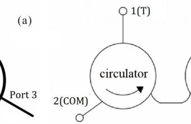
RF circulators are three-port, non-reciprocal passive devices that route energy in one direction around a loop of ports. In an ideal circulator, power injected into Port 1 exits Port 2 with zero loss, and nothing leaks to Port 3. Real hardware is less forgiving: every ferrite junction, conductor, and interface introduces attenuation known as insertion loss.
In modern radar, SatCom, 5G base stations, and high-power test systems, fractions of a decibel can decide whether a link budget closes or fails. Understanding what insertion loss is, which values are realistic, and how it is measured is essential for anyone selecting or designing RF circulators.
1. What Is Insertion Loss in an RF Circulator?
Insertion loss (IL) describes how much signal power is lost when a device under test (DUT) is inserted into a transmission path. For an RF circulator operating in its low-loss direction (for example, Port 1 → Port 2), insertion loss is defined as the ratio between output and input power, expressed in decibels:
IL(dB) = -10 · log10(P_out / P_in)
Because P_out is always slightly lower than P_in in a passive device, insertion loss is a positive number (for example, 0.25 dB). The same concept can be expressed in terms of voltage:
IL(dB) = -20 · log10(V_out / V_in)
For RF circulators and isolators, insertion loss captures all energy dissipated in the ferrite material, conductors, dielectrics, and transitions, as well as mismatch loss due to imperfect impedance matching.
2. Typical Insertion Loss Values for RF Circulators
High-quality RF circulators are designed so that the low-loss path exhibits only a few tenths of a decibel of attenuation across the specified frequency band. In the literature and datasheets, typical values are:
- About 0.2–0.4 dB for narrowband ferrite circulators and isolators in their passband.
- Around 0.1–0.5 dB as a common range cited for drop-in ferrite circulators.
- Roughly 0.2–0.75 dB in many practical microwave circulator and isolator implementations over their specified bandwidth.
- Up to ≈1.0–1.5 dB for very broadband units or devices operating close to their band edges.
The exact number depends on the operating frequency, bandwidth, physical structure (microstrip, stripline, drop-in, coaxial, or waveguide), ferrite material, and matching network design. A typical RF circulator specification table will list both a typical and a maximum insertion loss at the center frequency and over the full operating band.
2.1 Insertion Loss by Structure Type (Typical Ranges)
| Structure Type | Frequency Range (Example) | Bandwidth | Typical Insertion Loss |
|---|---|---|---|
| Waveguide circulator | X-band (8–12 GHz) | Narrowband (≈10% fractional) | ≈0.2–0.3 dB in band |
| Coaxial circulator | 100 MHz–6 GHz | Narrowband or octave | ≈0.2–0.5 dB |
| Drop-in ferrite circulator | L-band to Ku-band | 5–20% fractional | ≈0.2–0.6 dB |
| Microstrip/planar circulator | 1–40 GHz (design-dependent) | Often wideband | ≈0.3–0.8 dB, rising at band edges |
| Ultra-wideband designs | Multi-octave | Very wide | ≈0.8–1.5 dB typical |
In practical system design, engineers typically budget around 0.3–0.5 dB per circulator for narrowband designs, and slightly more when wide instantaneous bandwidth is required.
3. How Insertion Loss Is Measured (S-Parameters & VNAs)
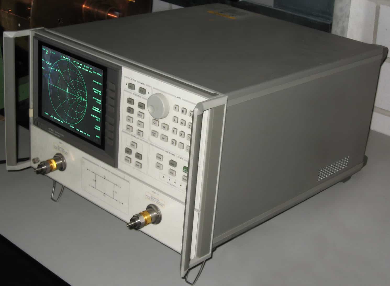
Insertion loss of an RF circulator is most commonly measured using a calibrated vector network analyzer (VNA) and expressed in terms of S-parameters. For a three-port circulator, the forward transmission from Port 1 to Port 2 is S21:
- Insertion loss (IL) ≈ −|S21| in dB for the low-loss direction (for example, 0.3 dB).
- Isolation is measured on the high-loss path (for example, S31 ≈ 20–30 dB for a circulator configured as an isolator).
3.1 Typical Measurement Setup
A standard measurement approach includes:
- Calibrate the VNA at the ends of the test cables using a suitable SOLT or TRL calibration kit.
- Connect Port 1 and Port 2 of the circulator to the two test ports with well-matched RF cables and adapters.
- Terminate Port 3 with a matched 50-ohm load to emulate real operating conditions.
- Sweep across the specified operating band and record |S21| in dB.
Careful calibration and de-embedding are important, because the loss in cables and adapters can be comparable to the circulator’s own insertion loss if not accounted for.
3.2 Narrowband vs. Broadband Characterization
For narrowband devices, a small frequency span around the center frequency (for example, ±5%) is typically enough to characterize insertion loss. For broadband or multi-octave circulators, full-band sweeps are needed to capture:
- Rise in insertion loss toward the band edges,
- Potential resonances due to internal structures,
- Temperature-dependent variations at different frequencies.
4. Key Factors That Drive Insertion Loss
Several physical and design parameters determine how low the insertion loss of a circulator can realistically be:
4.1 Frequency and Bandwidth
Loss in conductors, ferrites, and dielectrics increases with frequency. As the operating band moves from VHF/UHF into C-band, Ku-band, Ka-band and beyond, maintaining <0.3 dB loss becomes more challenging. Very broadband designs that must cover an octave or more will almost always exhibit higher insertion loss than optimized, narrowband devices.
4.2 Ferrite Material and Biasing
The ferrite material’s saturation magnetization, linewidth, and dielectric loss tangent directly affect how much RF energy is dissipated in the junction. Optimized, low-loss ferrites and carefully designed bias magnet structures can significantly reduce insertion loss, at the cost of increased complexity, size, or magnet weight.
4.3 Junction Geometry and Transmission Line Technology
Circulators can be implemented in:
- Waveguide – lowest loss, best high-power handling, larger physical size.
- Coaxial – convenient integration with cable systems, moderate loss.
- Drop-in or microstrip/stripline – compact, PCB-mountable, with slightly higher conductor and dielectric losses.
The geometry of the Y-junction and transitions between transmission-line types (for example, microstrip-to-coax) can introduce additional mismatch and ohmic loss if not properly optimized.
4.4 Impedance Matching and VSWR
Even with low internal dissipation, poor matching (high VSWR) will translate into apparent insertion loss because some energy is reflected back to the source instead of delivered to the next stage. Practical circulators target return loss better than 15–20 dB (VSWR <≈1.3) to minimize this contribution.
4.5 Power Handling and Temperature
At high average power, the power dissipated in the ferrite material is proportional to the insertion loss; this leads to self-heating and potential drift in characteristics if not cooled properly. High-power circulators may trade a slight increase in insertion loss for improved stability and reliability under load.
5. Design Trade-Offs: Loss vs. Isolation, Bandwidth, and Power
In circulator design, insertion loss never exists in isolation; it is tightly linked to other key parameters such as isolation, bandwidth, and power handling. Designers constantly balance:
- Insertion Loss vs. Isolation – Increasing isolation (for example, by stronger biasing or more complex matching networks) can add loss in the forward path if not carefully optimized.
- Insertion Loss vs. Bandwidth – Achieving very wide fractional bandwidth often requires more aggressive matching and more complex structures, which generally raises insertion loss.
- Insertion Loss vs. Power Handling – Structures optimized for high power may use thicker conductors, larger ferrite volumes, and specific materials that modify the loss profile.
- Insertion Loss vs. Size – Miniaturized microstrip or SMT circulators save board space but usually exhibit higher insertion loss than larger waveguide or coaxial units.
6. How Much Insertion Loss Is Acceptable in Real Systems?
The “right” insertion loss target depends on system-level constraints such as link budget, noise figure, and thermal margins. A few examples illustrate the impact:
6.1 Radar Transmit/Receive Modules
In AESA radar T/R modules, circulators often protect the power amplifier and allow duplex operation on a shared antenna. Every 0.5 dB of additional insertion loss on the transmit path reduces effective radiated power, while loss on the receive path worsens system noise figure. Designers therefore prefer narrowband, waveguide, or high-performance coaxial circulators with insertion loss well below 0.5 dB in the operating band.
6.2 SatCom and Microwave Backhaul Links
In SatCom and point-to-point microwave links, multiple passive components sit between the RF front-end and the antenna. A circulator with 0.4 dB insertion loss may be acceptable, but several devices in series (filters, switches, cables, connectors) can raise the total passive path loss to several decibels. Low-loss circulators help preserve link margin, especially in Ka-band where rain fade already erodes the budget.
6.3 Test & Measurement Systems
In high-precision measurement setups (for example, using a VNA to characterize devices behind a circulator), insertion loss adds uncertainty and reduces dynamic range. In this context, both the circulator and all associated cables are included in calibration or de-embedded to avoid corrupting measured S-parameters.
7. FAQ: Practical Questions Engineers Ask
Q1. Is lower insertion loss always better?
Generally yes, because lower insertion loss improves power efficiency and noise performance. However, aggressively minimizing insertion loss at all costs can compromise other parameters such as isolation, bandwidth, or power handling. A balanced design that meets the overall system specification is usually preferable to an extremely low-loss but narrow or fragile component.
Q2. Why do datasheets list both “typical” and “maximum” insertion loss?
Typical values represent the expected performance of nominal devices near the center of the band under standard conditions. Maximum values account for tolerances, temperature extremes, and performance at band edges. System designers should always close their link budget using the maximum guaranteed insertion loss.
Q3. How is insertion loss different from return loss?
Insertion loss measures attenuation through the device in the forward direction (Port 1 → Port 2), while return loss quantifies how much of the signal is reflected back toward the source due to impedance mismatch. A circulator with good insertion loss but poor return loss will still waste power and potentially create standing waves in the system.
Q4. Does insertion loss change with temperature and power?
Yes. Ferrite properties and conductor resistance are temperature-dependent, so insertion loss can drift as the device heats up. At very high power levels, additional non-linear effects and thermal gradients can further alter the loss profile. High-reliability designs therefore specify insertion loss across the full temperature and power range of interest.
8. About HzBeat – RF Circulator & Isolator Supplier (20 MHz–200 GHz)
HzBeat (Chengdu Hertz Electronic Technology Co., Ltd.) is a specialized RF and microwave component manufacturer focusing on high-performance ferrite circulators and isolators from 20 MHz up to 200 GHz. Our portfolio covers microstrip, drop-in, coaxial, waveguide and broadband solutions for radar, SatCom, 5G/6G, test & measurement, industrial and scientific applications.
For engineers who care about insertion loss, isolation, and reliability at the same time, HzBeat offers carefully optimized designs with low loss, high power handling, and stable performance across temperature.
- Microstrip Circulators & Isolators: compact, PCB-mount structures for phased-array radar, small cells, and integrated RF front-ends. Learn more: Microstrip Circulator Series.
- Drop-in Circulators: low-profile ferrite junctions with typical insertion loss in the 0.2–0.6 dB range, ideal for modular T/R modules and microwave subsystems. Product overview: Drop-in Circulator Products.
- Coaxial Circulators: convenient for cable-based RF systems, base stations, and test lines, with excellent power handling: Typical Coaxial Circulators.
- Waveguide Circulators: very low insertion loss and high peak power capability for radar, SatCom, and instrumentation: Waveguide Circulator Series.
If you are optimizing system insertion loss or need custom S-parameter targets for your project, our engineering team supports ODM customization based on your frequency band, power level, isolation requirement, and mechanical interface. Contact us to discuss your RF circulator or isolator design requirements.
Contact HzBeat: [email protected] · www.hzbeat.com
Relateds


About the Author

HzBeat Editorial Content Team
Marketing Director, Chengdu Hertz Electronic Technology Co., Ltd. (Hzbeat)
Keith has over 18 years in the RF components industry, focusing on the intersection of technology, healthcare applications, and global market trends.