Drop-in Isolators vs Coaxial Types: Design Comparison & HzBeat Product Guide
Updated on:
Keywords: Drop-in isolator, Coaxial isolator, RF circulator, HzBeat, microwave components, nonreciprocal devices, high-power RF, ferrite isolator
RF isolator design comparison between Drop-in isolator and Coaxial isolator types — a practical, engineering-first guide from HzBeat.
CC0 illustration created for HzBeat — visible inlined image, safe to reuse.
Introduction
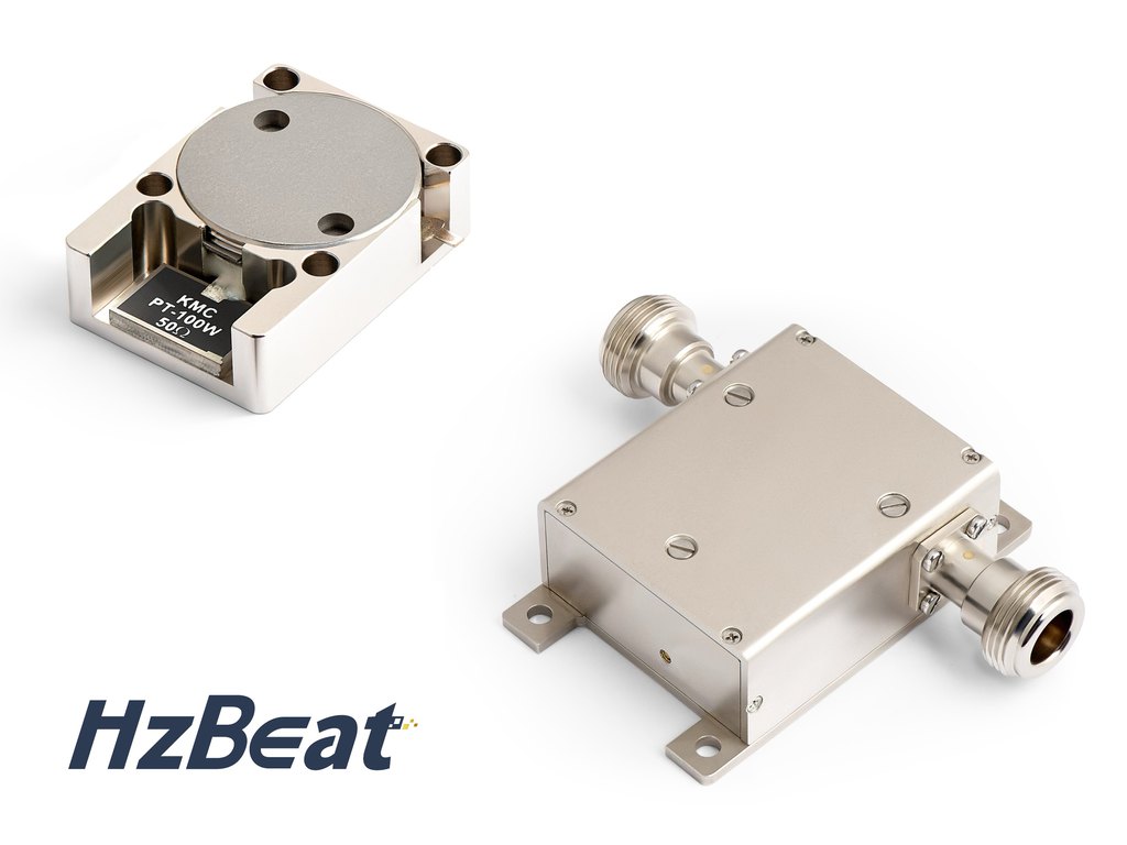
Selecting the right RF isolator in a modern microwave chain is a first-order design decision: form factor impacts insertion loss, isolation, VSWR, bandwidth, thermal handling, serviceability, and cost at scale. Engineers usually compare the Drop-in isolator — a board-mounted, compact module — with the Coaxial isolator — a connectorized, mechanically robust module — when optimizing nonreciprocal devices around the power amplifier, T/R modules, SATCOM terminals, and test systems.
This guide distills the structural differences, core RF metrics, and practical trade-offs. It also provides a brand-specific view by mapping the analysis to HzBeat product families. If your system requires a compact module embedded at PCB level, consider a drop-in isolator; if you need rugged connectorized integration and higher power margins, a coaxial isolator may be advantageous.
Principles of RF Isolators
An RF isolator is a two-port nonreciprocal device, typically realized by terminating the third port of a ferrite RF circulator. It allows forward power to pass with low insertion loss, while reflected power in the reverse direction sees a high isolation path and is absorbed by a matched load.
Key metrics:
insertion loss (IL), isolation (ISO), return loss / VSWR, fractional bandwidth, power handling (CW and peak), temperature stability, and size/weight.
Drop-in vs Coaxial: Structural Overview
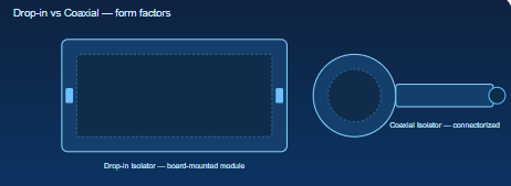
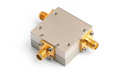
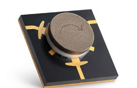
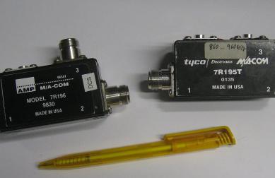
Form factor sketches: drop-in (left) integrates at PCB level; coaxial (right) uses connectorized housings.
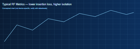
Conceptual metric trend: always verify with product datasheets for device-specific numbers.
A drop-in isolator eliminates connectors and reduces volume; the transition to PCB microstrip or stripline must be carefully matched to avoid parasitics that raise IL or degrade ISO at high microwave frequencies. A coaxial isolator integrates precision connectors and shields; it often improves repeatability and serviceability, especially in high-power RF environments, at the cost of added size and connector expense.
HzBeat Product Comparison Table
Representative models (verify exact values with official datasheets; contact HzBeat for tailored parameters).
| Type | Model | Frequency Range | Insertion Loss | Isolation | Typical Application |
|---|---|---|---|---|---|
| Drop-in | HMCTA80T120G | 8–12 GHz | Low (typ.) | High (typ.) | Board-level compact modules |
| Drop-in | HMCTB85T105G | 8.5–10.5 GHz | Low (typ.) | High (typ.) | Microwave link, phased arrays |
| Coaxial | HCITC450T1000M | 450–1000 MHz | Low (typ.) | High (typ.) | High-power PA protection |
| Coaxial | HMCYC18T26G | 18–26 GHz | Moderate (typ.) | High (typ.) | SATCOM, test subsystems |
Internal links:
HzBeat Drop-in (Isolators/Circulators) · HzBeat Coaxial (Isolators/Circulators)
Design Performance Analysis
Insertion loss and isolation
In a drop-in isolator, PCB transitions dominate; meticulous ground via fences, tapered impedance transformers, and minimized lead lengths preserve low IL. Connectorized coaxial isolators leverage controlled coax geometries, often showing excellent repeatability and robust ISO in production.
VSWR and bandwidth
Return loss is sensitive to transitions. Drop-in designs rely on board dielectric, stack-up, and pad geometry. Coaxial housings can be optimized across broader bands, but remember that overall bandwidth still depends on ferrite material, magnet bias, and matching networks.
Thermal and power handling
High-power RF requires attention to heat paths. Drop-in modules conduct into the PCB and chassis; adding copper coins, thermal vias, and heatsinks can be decisive. Coaxial housings allow larger thermal mass and direct chassis interface, easing continuous power dissipation.
Size, serviceability, and cost
Drop-in modules minimize volume and BoM for dense assemblies; field replacement is harder. Coaxial modules simplify module swaps and ATE setups but add connector cost and length/weight.
Application Recommendations
- Choose a drop-in isolator for compact T/R modules, phased arrays, or embedded SATCOM front-ends where PCB-level integration is paramount.
- Choose a coaxial isolator for high-power PA chains, lab instrumentation, and rugged systems where connectorized interchangeability is valuable.
- Consider hybrid strategies: drop-in at the module core + coaxial at system boundaries.
HzBeat Engineering Insights
HzBeat develops nonreciprocal devices — RF isolators and RF circulators — covering 20 MHz to 200 GHz. Design choices combine ferrite selection, magnet biasing, and precision machining with EM and thermal simulation. We support drop-in isolator and coaxial isolator form factors, and we collaborate with customers on mechanical envelopes, connectors, and PCB transitions.

Brand motif: “Connecting Frequencies in the World.”
Conclusion
The choice between a drop-in isolator and a coaxial isolator is system-driven: if you prioritize minimal footprint and PCB integration, drop-in shines; if your priority is high-power RF robustness and easy service, coaxial wins. With a balanced approach, engineers frequently deploy both across boundaries in the RF chain.
FAQ
Is a drop-in isolator always lower loss than a coaxial isolator?
Not necessarily. At high microwave frequencies, PCB transitions and parasitics can offset connector losses. Evaluate datasheets and prototypes across your band.
Do coaxial isolators support wider bandwidth?
They often can, thanks to controlled coax geometries and internal matching. Bandwidth still depends on ferrite composition, magnet bias, and circuit topology.
Where should I place an RF isolator for amplifier protection?
As close as possible to the PA output to suppress standing waves and reflected power — whether it is a drop-in or coaxial unit.
References
- Pozar, D. M., Microwave Engineering, Wiley — classic chapters on ferrite devices and nonreciprocal networks.
- Adam, J. D. et al., “Ferrite Devices and Materials,” IEEE Transactions on Microwave Theory and Techniques.
- MDPI Open Access articles on ferrite RF circulator / RF isolator design (CC-BY licensed).
- HzBeat official site — Drop-in · Coaxial portfolios.
Relateds


About the Author

HzBeat Editorial Content Team
Marketing Director, Chengdu Hertz Electronic Technology Co., Ltd. (Hzbeat)
Keith has over 18 years in the RF components industry, focusing on the intersection of technology, healthcare applications, and global market trends.