RF Front-End Optimization with Attenuators & Isolators for Microwave Systems
Updated on:
Keywords: RF attenuator, RF isolator, RF front-end optimization, microwave systems, signal integrity,
When Precision Meets Protection in High-Performance RF Design
Consult Custom Attenuator/Isolator About HzBeat
Table of Contents
- Introduction — Precision, Protection, Stability
- Understanding the RF Front-End Chain
- Isolators: Nonreciprocal Protection Against Reflections
- Isolators: Nonreciprocal Protection Against Reflections
- Integration: When Attenuators & Isolators Work Together
- Design Considerations for High-Performance Microwave Systems
- FAQ
- References
Introduction — Precision, Protection, Stability
Modern microwave systems—from 5G/6G radio units to radar and satellite communication links—demand meticulous RF front-end optimization. Two humble but decisive components, attenuators and isolators, often determine whether your link budget, linearity, and power survivability meet specification. In practice, they turn “nice lab plots” into field-ready performance.
TL;DR:
Use attenuators to set and stabilize gain (protecting linearity and test repeatability); use isolators to decouple stages and suppress reverse power (protecting PAs and stabilizing matching). Together, they raise signal integrity, power stability, and system reliability.
Understanding the RF Front-End Chain
A typical front-end chain combines power amplification, filtering, gain control, and nonreciprocal protection. Key roles:
- Attenuator — trims level, linearizes dynamic range, equalizes channel gain.
- Isolator — ensures one-way power flow, mitigates VSWR-induced oscillation and PA damage.
- Filters — constrain out-of-band content; interplay with attenuator for noise figure.
In production and verification, calibrated attenuators and high-isolation devices simplify repeatable measurements and reduce the sensitivity to connector/fixture variations.
Isolators: Nonreciprocal Protection Against Reflections
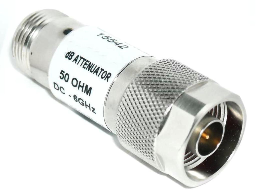
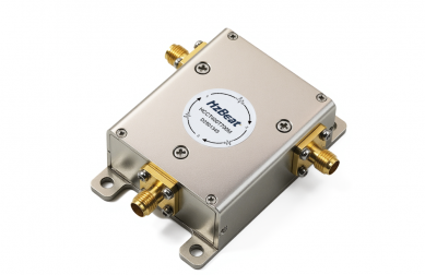
Figure. RF fixed attenuator (coaxial). Product photo, CC source with credit link. Source: L-com / BigCommerce product image page. Check site terms for usage permissions.
Function and Types
Attenuators reduce signal amplitude in a controlled manner to prevent compression, extend dynamic range, and stabilize gain. Common types include fixed pads (e.g., 3/6/10/20 dB), step attenuators, and voltage/TTL-controlled or digital attenuators for AGC loops.
Key Parameters
- Nominal Attenuation & flatness across band (e.g., ±0.5 dB).
- Insertion Loss of the device body (≠ attenuation value), impacts noise figure.
- VSWR/Return Loss — matching at both ports, affects ripple and stability.
- Power Handling — average & peak; derating with temperature.
Isolators: Nonreciprocal Protection Against Reflections
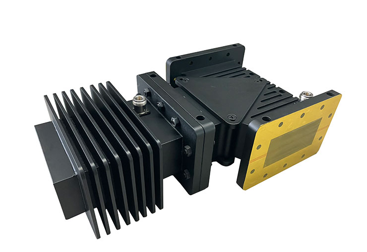
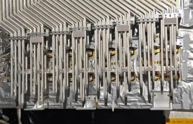
Figure. Waveguide isolator. Product photo, CC source with credit link. Source: Dolph Microwave product page. Confirm license or obtain permission.
Why Nonreciprocity Matters
Ferrite-based isolators/circulators exploit magnetically biased gyromagnetic effects to create a one-way path. Reflected power from antennas/filters is absorbed or redirected, preventing gain peaking or oscillation and protecting sensitive or high-cost devices such as PAs, LNAs, and synthesizers.
Key Parameters
- Isolation (e.g., >20–25 dB chain-level; >30 dB device-level for narrowband).
- Insertion Loss (target low; balance vs. bandwidth and magnetics volume).
- Power Rating (CW/peak); thermal path and magnet bias stability.
- Bandwidth vs. size & material choices (e.g., Ku/Ka-band waveguide vs. microstrip).
Integration: When Attenuators & Isolators Work Together
In a transmit chain, a fixed attenuator before the PA linearizes drive, while an isolator after the PA shields against antenna mismatch (→ improved EVM/ACLR in communication systems and phase stability in radar/sensing). In test chains, placing an isolator between a DUT and a step attenuator stabilizes the analyzer input match, improving repeatability.
- Phased-array T/R modules: isolate PA outputs per element; trim amplitude/phase with fine-step attenuators.
- 5G/6G radio units: stabilize front-end filters and active devices across temperature and load variations.
- Satellite links (K/Ka band): protect high-value payload PAs and control loop dynamics.
HzBeat inside:
Explore drop-in, microstrip, waveguide nonreciprocal components and custom matching to your chain requirements.
Design Considerations for High-Performance Microwave Systems
Layout & Matching
Keep transitions short; control reference-plane definition; budget return loss and ripple. For microstrip/SIW, pay attention to via fences and ground integrity. For waveguide, flange flatness and torque repeatability affect isolation and IL at Ka-band.
Thermal & Reliability
Power derating curves and magnet bias temperature coefficients dictate isolation across environment. Provide low-impedance thermal paths, especially for high-CW attenuator loads and output isolators.
Bandwidth & Materials
At Ku/Ka-band, ferrite properties, magnet topology, and junction geometry govern the trade between isolation, IL, and size. For attenuators, resistor films and substrate coefficients set flatness and PIM.
FAQ
Can an isolator replace a circulator?
No. An isolator is effectively a 2-port one-way device. A circulator is a 3-port router (e.g., Tx→Ant, Ant→Rx) and supports duplexing/routing functions. In some protection-only cases, an isolator suffices; for simultaneous Tx/Rx paths, a circulator or dedicated duplexer is required.
How do I choose attenuation value?
Start from your linearity budget (compression point/EVM) and the desired dynamic range; then simulate the chain-level NF/IL impact. Typical fixed values are 3–10 dB for match taming, with step attenuators providing calibration range.
What frequency ranges are practical?
For coax/microstrip isolators, L–Ku are common; waveguide covers Ku/Ka and beyond. Attenuators span DC to tens of GHz; specify connectors (SMA, N, 2.92 mm, etc.) and power ratings accordingly.
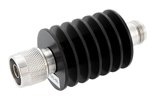
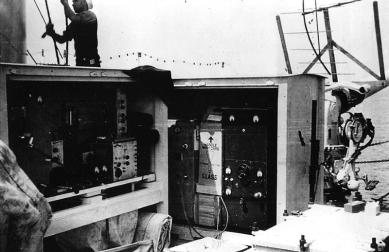
Figure. High-power RF attenuator with heatsink. Product photo, CC source with credit link. Source: Pasternack product page. Confirm license or obtain permission.
References
- L-com / BigCommerce product photo (coaxial attenuator): Image. Check usage terms.
- Pasternack PE7426-40 (product page and datasheet for reference): Product, Datasheet PDF.
Relateds


About the Author

HzBeat Editorial Content Team
Marketing Director, Chengdu Hertz Electronic Technology Co., Ltd. (Hzbeat)
Keith has over 18 years in the RF components industry, focusing on the intersection of technology, healthcare applications, and global market trends.