X-Band RF Circulator/Isolator – Microstrip, Drop-In, Coaxial, Waveguide
Updated on:
Keywords: X-band RF circulator, X-band RF isolator, X-band circulator isolator, microstrip circulator, drop-in circulator, coaxial isolator, waveguide circulator, radar, SatCom
A practical guide to X-band RF circulators and isolators across microstrip, drop-in, coaxial, and waveguide implementations – how they protect power amplifiers, improve VSWR, and keep modern radar and satellite links stable.

1. Why X-Band Needs Reliable RF Circulators and Isolators
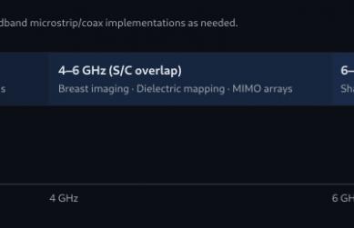
X-band, typically defined as 8–12 GHz, sits in a sweet spot of the microwave spectrum. It offers a powerful combination of resolution, antenna size, and propagation characteristics, which is why it is widely used in traffic and weather radar, coastal surveillance, UAV payloads, and secure satellite communication links.
In all these systems, the X-band RF circulator and isolator are far more than “just another ferrite device” on the bill of materials. They act as:
- Directional traffic controllers – forcing RF energy to follow the intended signal path.
- Guardians of the PA – protecting solid-state power amplifiers from destructive reflections.
- Stability anchors – maintaining predictable VSWR, gain, and noise performance over time.
As X-band systems migrate toward higher power, tighter form factors, and more integration, choosing the right X-band RF circulator/isolator – and the right package type – becomes a genuine system-level decision, not a last-minute accessory.
2. What an X-Band RF Circulator/Isolator Does in Real Systems
A 3-port X-band RF circulator typically routes RF power from port 1 → port 2, port 2 → port 3, and port 3 → port 1 in a fixed direction. When one port is terminated with a matched load, the circuit becomes an isolator, allowing power to flow in only one direction while strongly attenuating reverse energy.
In X-band radar and SatCom designs, this translates into three very practical functions:
- Duplexing: Sharing a single antenna between transmit and receive chains, especially in pulse radar, FMCW radar, and transceiver front ends.
- PA protection: Absorbing reflected power from mismatched antennas, radomes, or waveguide structures to improve long-term reliability of GaN/GaAs amplifiers.
- System linearity and sensitivity: Keeping reflections low helps maintain predictable gain, SNR, and dynamic range over temperature and time.
3. Four Key Implementations: Microstrip, Drop-In, Coaxial, Waveguide
Most X-band RF circulators and isolators fall into one of four main mechanical implementations: microstrip, drop-in, coaxial, and waveguide. Each construction style brings its own balance of size, power handling, integration effort, and cost.
3.1 Microstrip X-Band Circulators/Isolators
Microstrip X-band circulator/isolator devices are designed to mount directly on printed circuit boards. They are often the first choice when:
- Board-level integration and low profile are critical.
- The design targets compact radar modules, UAV payloads, or phased-array tiles.
- Power levels are moderate, and line replaceable units (LRUs) are tightly packed.
Microstrip solutions can be tuned for narrowband or moderate bandwidth operation, and they excel in highly integrated T/R modules where every square millimetre of PCB area counts.
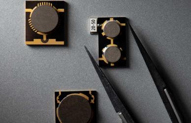
3.2 Drop-In X-Band Circulators/Isolators
Drop-in X-band circulators and isolators are compact ferrite devices that sit in a milled cavity or cut-out, with RF connections made via microstrip, stripline, or bond wires. Engineers typically select drop-in parts when they need:
- Better thermal management than pure microstrip solutions.
- More robust mechanical support in vibration-prone environments.
- Low insertion loss and good isolation in a compact footprint.
Drop-in X-band RF circulator/isolator devices are common in power amplifier modules, receiver protectors, and integrated microwave assemblies where board-level integration is important but pure PCB-mounted devices would be too fragile.
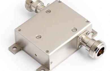
3.3 Coaxial X-Band Circulators/Isolators
Coaxial X-band RF circulators/isolators use standard coax connectors (often SMA or K-type) and are ideal for:
- Laboratory test setups and rapid prototyping.
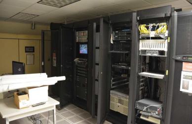
- Rack systems where cables route between modules.
- Subassemblies that may be replaced or upgraded independently.
Coaxial devices tend to offer a good balance between ease of use, bandwidth, and ruggedness. They are a natural choice when the X-band signal path is largely coaxial or when the design team values flexibility and field-serviceability.
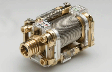
3.4 Waveguide X-Band Circulators/Isolators
Waveguide X-band circulators and isolators are the workhorses of high-power radar and SatCom systems. By confining RF energy in a WR-90 or similar rectangular waveguide, they deliver:
- Very low insertion loss over the intended X-band window.
- High peak and average power handling.
- Excellent isolation and VSWR performance.
When the system architecture uses X-band waveguide for the main RF path – for example in high-power shipborne radar, ground-based tracking radar, or earth station up/downlinks – waveguide circulators and isolators are typically the most reliable solution.

4. Key X-Band RF Specifications to Compare
No matter which mechanical format you choose – microstrip, drop-in, coaxial, or waveguide – engineers should evaluate the same core RF parameters when selecting an X-band RF circulator/isolator:
| Parameter | Typical X-Band Targets | Why It Matters |
|---|---|---|
| Frequency Range | 8–12 GHz, often centred around radar or SatCom channels | Must fully cover operating band with margin for drift and manufacturing tolerance. |
| Insertion Loss | ≤ 0.4–0.6 dB (high-performance paths) | Directly impacts radar range and link budget; especially critical in receive chains. |
| Isolation | ≥ 18–23 dB, higher for demanding systems | Improves PA protection and reduces reflected energy into sensitive receiver stages. |
| Return Loss / VSWR | VSWR 1.20–1.30:1 typical | Better matching means fewer standing waves and more predictable system behaviour. |
| Power Handling | From a few watts to hundreds of watts CW / kW-level peak | Essential for high-power pulse radar and long-range communication links. |
| Temperature Range | –40 °C to +85 °C or +125 °C | Required for outdoor, airborne, and defence environments. |
| Form Factor | Microstrip, drop-in, coaxial, waveguide | Determines routing, integration effort, and serviceability. |
For search engines, this section naturally reinforces long-tail queries such as X-band RF circulator specifications X-band RF isolator power rating 8–12 GHz circulator while still reading like a human-friendly engineering checklist.
5. Application Scenarios Across Package Types
The four implementation types map naturally into different X-band application spaces:
- Microstrip: compact phased-array tiles, UAV payloads, embedded radar sensors, automotive and industrial X-band radar.
- Drop-In: power amplifier modules, receiver protectors, compact LRUs, and ruggedized subassemblies with cavity-mounted ferrite devices.
- Coaxial: flexible prototypes, test equipment, benchtop radar demonstrators, and rack-mount signal chains.
- Waveguide: long-range surveillance radar, tracking radar, coastal radar, high-power shipborne and ground-based systems, and X-band SatCom earth stations.

6. How to Select the Right X-Band RF Circulator/Isolator
When selecting an X-band RF circulator or isolator, treat the decision as a system-level trade-off between performance, size, cost, and integration. A practical short-list:
- Define the exact X-band channel(s) (for example 9.3–9.5 GHz or 10.25–10.55 GHz).
- Separate TX and RX requirements – power handling and insertion loss targets may differ.
- Choose the mechanical format that aligns with your architecture: microstrip, drop-in, coaxial, or waveguide.
- Set minimum acceptable isolation and VSWR across temperature.
- Check whether an existing catalog part works or whether custom tuning is needed.
Many modern designs end up using a mix: for example, a waveguide X-band circulator on the main high-power path, combined with microstrip or drop-in isolators inside compact T/R modules.
7. X-Band RF Circulator/Isolator with Custom Microstrip, Drop-In, Coaxial & Waveguide Solutions
Custom X-Band Solutions from 20 MHz to 200 GHz
HzBeat focuses on RF circulators and isolators from 20 MHz up to 200 GHz, with dedicated product lines for microstrip, drop-in, coaxial, and waveguide devices. For X-band, we support:
- Standard and wideband X-band RF circulators/isolators.
- Compact microstrip and drop-in designs for high-density modules.
- Coaxial devices for test, integration, and flexible system routing.
- High-power waveguide X-band components for radar and SatCom.
For engineers working on long-cycle or high-difficulty projects, we provide custom design and ODM support: from early specification and electromagnetic modelling to sample tuning and small-batch pilot runs.
You can explore our related product families here:
Looking for a specific X-band RF circulator/isolator design (for example 9.3–9.5 GHz or 10.25–10.55 GHz)? Share your target band, power level, and size constraints, and we can help you evaluate whether a catalog or fully custom solution is the best fit.
8. FAQ: X-Band RF Circulators & Isolators
Q1. What frequency range does “X-band” usually cover?
In most radar and satellite communication contexts, X-band covers approximately 8–12 GHz. Specific systems may use narrower sub-bands centred on allocated channels, such as 9.3–9.5 GHz for marine radar or around 10 GHz for traffic and speed monitoring.
Q2. When should I use a microstrip vs. a waveguide X-band circulator?
Use microstrip X-band circulators/isolators when you need tight PCB integration, low profile, and moderate power handling – for example in compact radar sensors or T/R modules. Choose waveguide X-band circulators/isolators when your system runs at high power and already uses waveguide for the main RF path, such as in long-range surveillance radar or X-band SatCom earth stations.
Q3. What insertion loss is acceptable for an X-band RF isolator?
For high-performance radar or communication receivers, many designers target ≤ 0.4–0.6 dB insertion loss for X-band RF isolators and circulators. Slightly higher values can be acceptable in high-power transmit paths, but every fraction of a decibel matters in the overall link budget.
Q4. Can I mix different package types in one X-band system?
Yes. It is common to combine, for example, a waveguide X-band circulator at the antenna interface with microstrip or drop-in isolators deeper in the RF chain. The important point is to keep the overall impedance environment controlled and to ensure that each device is correctly matched and rated for the local power level.
Q5. Do I always need a dedicated X-band RF isolator for PA protection?
If your transmitter sees significant load mismatch or if the antenna environment can change over time (ice, rain, radome damage, mobile platforms), a dedicated X-band RF isolator is strongly recommended. In tightly controlled environments with low power, some designers accept a higher risk level, but for mission-critical radar and SatCom links, reverse power protection is considered standard good practice.
Relateds
About the Author

HzBeat Editorial Content Team
Sara is a Brand Specialist at Hzbeat, focusing on RF & microwave industry communications. She transforms complex technologies into accessible insights, helping global readers understand the value of circulators, isolators, and other key components.