The Origins and Evolution of the RF Circulator
Updated on:
Keywords: RF circulator,ferrite circulator,non-reciprocal devices,microwave engineering,radar history,satellite communication,Faraday rotation,Y-junction circulator,HzBeat factory,China RF supplier
In every era of wireless progress there is a quiet workhorse safeguarding transmitters, amplifiers, and antennas: the RF circulator. It does not boast, but it decides where energy may go. This is the origin story of a device that turned physics into engineering—and engineering into connection.
Introduction — When Physics Learnt to Say “One-Way Only”
In 1845 Michael Faraday discovered that a magnetic field could twist light’s polarization—the Faraday effect. He had no radio to tune, no satellite to call; only a glimpse that magnetism might bias waves into a preferred direction. A century later, that intuition reached the microwave realm. Ferrites—ceramics with aligned electron spins—could be biased by a permanent magnet to make microwaves behave non-reciprocally: favoring one direction over another. Out of this asymmetry grew the RF circulator, a quietly heroic component that lets a transmitter speak without letting echoes shout back.
The circulator is, at heart, a story of turning a subtle material property into a robust industrial product. Its earliest blueprints came from waveguide benches and radar vans. Its maturity came in the stripline and microstrip labs of the 1960s. Its miniaturization now rides with 5G, satellite constellations, and new topologies that imitate ferrites in silicon. What follows is a journey through ideas, hardware, and the people who wanted signals to move forward—cleanly, safely, and efficiently.
1) The Physical Seed: Faraday Rotation & Ferrite Non-Reciprocity
The circulator could not exist without magnetically biased ferrites. Apply a static magnetic field, and the material’s permeability becomes a tensor. When a microwave passes through, its polarization can rotate in a direction that depends on propagation relative to the bias—this is the microwave cousin of Faraday’s optical discovery. In waveguides and junctions, that rotation translates into phase asymmetry between ports. Engineer the geometry and loading correctly, and power entering one port flows to the next port clockwise, but not back to where it came from.
- Ferrite disks or slabs placed in a resonant junction create gyrotropic phase shifts.
- Bias magnets (often permanent) set the operating point; temperature and frequency determine stability.
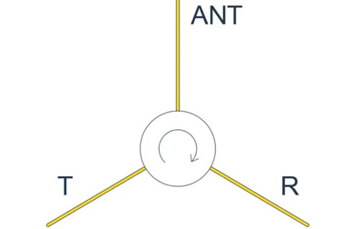
- The classic 3-port Y-junction is the most recognizable embodiment; 4-port versions often follow as two cascaded 3-ports.
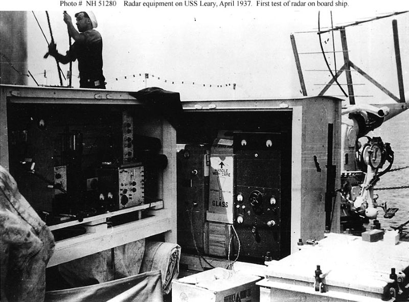
2) Wartime Radar and the Birth of Practical Circulators
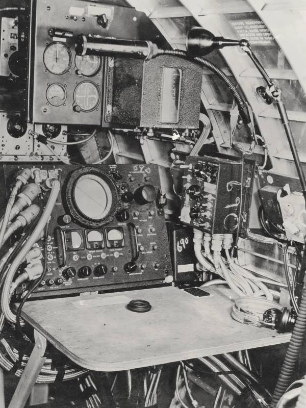
World War II created a ferocious need to manage power: magnetrons were loud, reflections were lethal to fragile front-ends, and radar needed clean duplexing. Early ferrite components first appeared as gyrators and isolators in bulky waveguides. The circulator emerged as a compact way to route energy in one rotational direction among three ports—transmitter, antenna, receiver—without resorting to moving parts.
By the mid-1950s, Bell Labs and European groups had established rigorous theory for ferrite behavior at microwave frequencies. Manuals from the era—dense with TE/TM modes and field plots—read like field notes from explorers mapping a new continent: insertion loss shaved by tenths, isolation gained by dB, all hard-won with magnets, machining, and patience.
The first widely disseminated stripline Y-junction circulator designs in the early 1960s were a turning point. They preserved the non-reciprocal magic of waveguides but promised lighter, flatter, and—eventually—cheaper modules suitable for commercial communication equipment.
3) From Waveguide to Stripline and Microstrip — An Engineering Migration
Waveguide circulators felt at home in radar rooms and satellite earth stations: heavy, rugged, astonishingly power-capable. But the industry dreamed of printed circuits. Stripline and later microstrip designs transplanted the ferrite disk into planar geometries, trimming metal and mass. The 1960s–1980s saw a steady march toward lower insertion loss, higher isolation, and reliable bias control in compact packages—from rack drawers to daughtercards.
Key design levers in planar circulators:
- Ferrite composition & saturation magnetization — tunes the resonance and bandwidth.
- Disk radius/thickness and junction geometry — control modal coupling and match.
- Bias magnetic circuit — from bulky rings to clever pole-piece shaping for uniform bias.
- Matching networks — quarter-wave transformers, capacitive pads, or dielectric ramps.
Not every migration was painless. Planar layouts faced spurious modes, temperature drift, and tight manufacturing tolerances at higher bands. Yet the direction of travel was set: miniaturize without sacrificing the one promise customers truly buy—predictable non-reciprocity.
4) The Human Side — Labs, Lathes, and Low-Noise Dreams
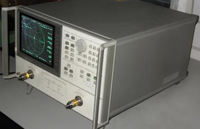
The circulator’s history is full of small human rituals: a technician stoning a flange flat to chase the last tenth of a dB, an engineer aligning magnets while watching a VNA trace steady, a buyer arguing lead times for ferrite pucks with the patience of a sculptor waiting on marble. These scenes repeat from Cold War labs to today’s contract manufacturers. The device may be modest, but its failure is spectacular—smoked amplifiers, detuned arrays, service calls at 3 a.m. This is why seasoned RF teams talk about isolators and circulators with a reverence usually reserved for fuses and saints.
5) Where Circulators Work — A Short Atlas of Applications
- Radar front-ends — guarding low-noise receivers from high-power transmit pulses.
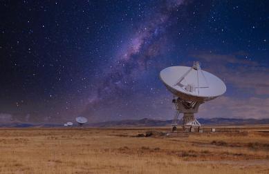
- Satellite & deep-space links — duplexing and protecting TWTAs/SSPAs with strict linearity demands.
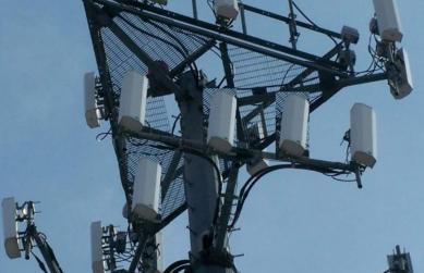
- Base stations & small cells — managing reflections across crowded bands in 4G/5G.
- Industrial & scientific — MRI, particle accelerators, and precision material processing.
- Cryogenic & quantum labs — leveraging non-reciprocity in delicate measurements.
In each domain the calculus is similar: keep insertion loss low so power budgets hold, keep isolation high so sensitive stages survive, and keep VSWR friendly so systems behave politely under mismatch.

6) Anatomy of Performance — IL, ISO, Power, and Bandwidth
| Parameter | Why it matters | Typical considerations |
|---|---|---|
| Insertion Loss (IL) | Defines heat, EIRP, NF penalty. | Ferrite quality, surface finish, matching topology. |
| Isolation (ISO) | Protects PA/LNA; prevents oscillation. | Bias uniformity, modal purity, termination quality. |
| VSWR/Return Loss | System stability and amplifier comfort. | Port matching, flange flatness, connector care. |
| Power Handling | Avoids ferrite heating and demagnetization. | Thermal path, ferrite saturation, duty cycle. |
| Bandwidth | Accommodates wide standards and chirps. | Multi-disk tricks, asymmetric junctions, materials. |
7) Milestones & Turning Points — From Bell Labs to Silicon Experiments
- 1950s: Microwave ferrite theory matures; waveguide gyrators/isolators standardize.
- Early 1960s: The stripline Y-junction circulator takes hold; planarization accelerates.
- 1980s–1990s: High-power Y-junction waveguide classes deliver megawatt handling for accelerators and broadcast.
- 2000s–2010s: Wideband tactics (multi-disk, asymmetric junctions) broaden utility; systems shrink while specs tighten.
- 2016→: Academic prototypes demonstrate time-modulated/switch-based “ferrite-less” circulators on chip—an echo of the old dream of non-reciprocity without magnets.
Will silicon displace ferrites? In narrow, integrated niches, yes. In high-power, high-linearity, high-reliability arenas, classic ferrites remain sovereign. The future looks hybrid: keep ferrites where physics rewards them; use clever switching where integration wins.
8) Manufacturing Notes — What Great Factories Actually Do
Behind every low-loss spec is a procession of quiet excellences: ferrite lot control, magnet fixture repeatability, lap-and-polish recipes for metal surfaces, probe-station discipline on S-parameters, and burn-in that flushes the weak. Great factories do not merely assemble—they stabilize materials and geometry until the device’s non-reciprocity becomes boringly reliable. That boredom is the customer’s favorite feature.
- Lot-to-lot ferrite characterization to pin IL/ISO center.
- Magnetic bias mapping for uniformity across the junction.
- Thermal stack design for power headroom and longevity.
- VNA calibration culture—because a bad cal looks like bad physics.
Practical tip: if ISO drifts with temperature, interrogate the magnet path and ferrite Curie margin before you blame the matching network.
9) Choosing the Right Circulator — A Short Buyer’s Compass
- Band & Bandwidth: Map to regulatory masks and waveform crest factors.
- Power & Duty Cycle: Guard against ferrite heating and demagnetization.
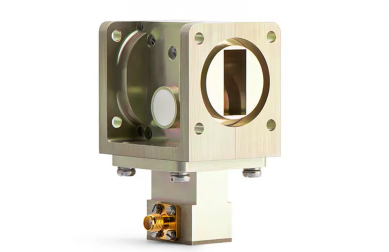
- Form Factor: Waveguide for power, microstrip/stripline for compactness; drop-in as a happy middle.
- Environment: Temperature cycles, vibration, altitude—magnets remember.
- Lifecycle: Consider re-tuning options and EOL ferrite availability.
Conclusion — The Quiet Arrow in the RF Quiver
The RF circulator began as a physics curiosity and became an industrial covenant: power shall pass; reflections shall not return. From wartime waveguides to today’s mmWave labs, it embodies a modest miracle—useful asymmetry. As wireless systems multiply, this quiet arrow will keep flights true.
FAQ
Relateds

About the Author

HzBeat Editorial Content Team
Sara is a Brand Specialist at Hzbeat, focusing on RF & microwave industry communications. She transforms complex technologies into accessible insights, helping global readers understand the value of circulators, isolators, and other key components.