How Does an RF Circulator Work?
Formal, engineering-focused explainer of RF circulators: working principles, ferrite non-reciprocity, formats (SMT, drop-in, coaxial, waveguide), key specs, integration tips, testing, and applications across 5G, radar, and satellite.
RF circulators—also known as ferrite circulators or microwave circulators—are the quiet enablers of reliable high-frequency systems. Deployed between a power amplifier and an antenna, the device ensures that forward power travels to the load while any reflected energy is routed away from sensitive circuitry. In modern infrastructure—5G/6G radios, radar front‑ends, satellite communications (SATCOM), and microwave test benches—a well‑matched circulator improves uptime, reduces warranty risk, and stabilizes overall VSWR. In short, without a robust circulator, many “always‑on” RF links would be uniquely vulnerable to mismatch, detuning, and transients.
Introduction: Why RF Circulators Matter
From a system architect’s perspective, the circulator acts like a one‑way rotary junction: Port 1 → Port 2 → Port 3 → Port 1. A common use case is to terminate Port 3 with a 50‑ohm load so that any reflected power from the antenna is safely absorbed, protecting the PA. Engineers often pair the circulator with directional couplers, limiters, and power detectors to implement protection loops and field diagnostics.
Working Principle: Ferrite Non‑Reciprocity and Magnetic Bias
At microwave frequencies, ferrites such as YIG exhibit gyromagnetic behavior under a DC magnetic bias, making the permeability tensor non‑symmetric. The consequence is non‑reciprocal transmission: electromagnetic modes traversing the ferrite junction experience direction‑dependent phase evolution, which favors energy transfer from one port to the next while attenuating reverse flow. The sense of circulation—clockwise or counterclockwise—is set by the bias polarity and ferrite geometry.
- Ferrite Junction: Typically a disk or resonant junction around which microstrip, stripline, coaxial, or waveguide fields couple. Material composition and saturation magnetization define the operating window.
- Magnetic Bias: Permanent magnets or electromagnets establish the bias field. Uniformity of the field strongly impacts isolation and insertion loss (IL).
- Matching Network: Capacitive/inductive elements and the mechanical stack‑up (ceramics, substrates, conductors) are tuned to achieve a 50‑ohm interface across temperature.
Device Formats: SMT, Drop‑in, Coaxial, and Waveguide
While the physics is shared, mechanical format defines integration strategy, thermal path, and power envelope. Selecting the right style up‑front reduces redesign cycles and BOM churn:
SMT / Microstrip Circulators
Chosen for compact radios and integrated modules, SMT circulators mount directly on RF PCBs. They emphasize miniaturization, low IL, and consistent matching. Designers must budget for copper pour, keep‑out regions, thermal vias, and solder reflow profiles. Typical use cases include massive‑MIMO radios and compact backhaul links.
Drop‑in Circulators
Drop‑ins provide a rugged mechanical interface and repeatable ground reference. They fit well in hybrid assemblies where thermal anchoring and mechanical stability are important, e.g., airborne radar, EW, or high‑vibration platforms. The format simplifies maintenance and replacement compared with fully embedded SMT options.
Coaxial Circulators
Coaxial units provide broadband performance, robust connectors (SMA/N‑type/7‑16), and ease of testing. They are common in transmit chains, RF distribution, and measurement setups. The trade‑off is volume—coaxial housings are typically larger than SMT or drop‑ins.
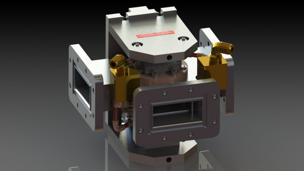
Waveguide Circulators
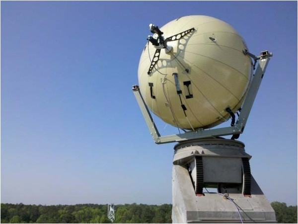
For high‑power or ultra‑low‑loss applications, waveguide circulators dominate. The conductive waveguide walls reduce loss and improve thermal handling at high field intensities. Antenna feed networks, long‑range radar, and SATCOM gateways are typical domains.
Key Performance Metrics and Typical Targets
| Metric | Definition / System Impact | Typical Targets |
|---|---|---|
| Insertion Loss (IL) | Forward path loss. Impacts PA back‑off, EIRP, and link margin. | 0.1–0.5 dB (format and band dependent) |
| Isolation | Attenuation between non‑adjacent ports (e.g., 1→3). Protects PA and reduces RX desense. | ≥20–25 dB standard; ≥30 dB premium |
| Return Loss / VSWR | Matching to 50 Ω. Poor match increases ripple, heating, and spurs. | ≤1.2:1 to 1.5:1 over temp |
| Power Handling | Maximum CW/peak without degradation. Critical for pulsed radar. | Up to hundreds of watts; kW‑class in waveguide |
| Bandwidth | Frequency span meeting spec. Influences multi‑band readiness. | Narrowband to octave‑plus |
| Temperature Stability | Spec drift vs. environment. Magnet/ferrite properties vary with T. | −40 °C to +85 °C typical (custom outside) |
Integration and Thermal Design
Regardless of format, circulator performance is tightly coupled to the surrounding stack‑up. For SMT designs, maintain short, well‑controlled microstrip/stripline transitions, include ground vias to reduce current loops, and study PCB copper balance to avoid warpage during reflow. For drop‑in and coaxial parts, plan a direct thermal path (heatsink or chassis) and minimize discontinuities at connectors. Waveguide units benefit from precise flange alignment and proper screw torque to maintain contact integrity; avoid paint or gaskets that increase RF contact resistance unless specifically required.
- Termination Strategy: Decide whether Port 3 uses an internal or external load. External loads facilitate field replacement and power scaling.
- EMC & Coexistence: In dense platforms, use absorbers or shielding around high‑Q cavities to suppress parasitic coupling and IMD.
- Simulation vs Reality: Correlate 2.5/3D EM models with fixtured measurements; include connector launch and housing effects in the model.
Applications by Vertical
- 5G/6G & Small Cells: PA protection, duplexing assistance, and mismatch buffering in compact radios; preference for SMT/microstrip to reduce BOM and footprint.
- Radar & EW: High‑power handling and low insertion loss for pulsed chains; waveguide and rugged drop‑ins dominate airborne and naval platforms.
- SATCOM Gateways & Ground Stations: Low‑loss paths and reliable isolation across wide temperature swings; often a mix of coaxial and waveguide.
- Medical (MRI/NMR): Stable performance in strong fields and controlled environments; bespoke magnetization profiles may be needed.
- Quantum/Cryogenics: Low‑noise, low‑loss chain elements interfacing with cryo stages; careful thermal anchoring and magnetic shielding recommended.
Validation and Reliability Testing
Production programs rely on repeatable, traceable testing to guarantee field performance. Typical flows include:
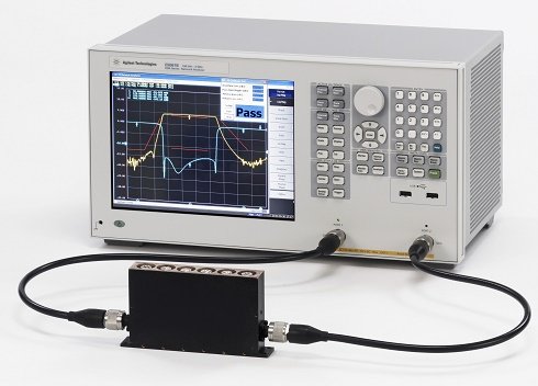
- S‑Parameter Verification: SOLT/TRL calibration, port‑power sweep, and time‑gating for fixture de‑embedding. Capture IL, isolation, and return loss across temp.
- Power & Thermal Endurance: Step‑stress at rated CW/peak power; monitor temperature rise, magnetic drift, and permanent changes in IL/isolation.
- Thermal Cycling & Storage: Ensure magnet and ferrite properties remain within tolerance after repeated cycles and long storage.
- Vibration/Shock: For defense and aerospace, verify integrity of magnets, fasteners, solder joints, and connectors.
- Incoming Quality Control (IQC): Lot‑to‑lot variation tracking with SPC; maintain serial‑level test records for root‑cause analysis.
Selection Checklist
- Define bandwidth, power, and VSWR targets early; characterize antenna/load behavior over temperature.
- Select the format that fits power density and mechanical constraints (SMT vs drop‑in vs coaxial vs waveguide).
- Balance IL vs isolation: optimize for link budget and PA survivability, not just a single best‑case number.
- Confirm termination strategy and available space for heat sinking of the load.
- Request worst‑case data and lifetime stress results, not only typical curves.
Related Product Families
- Microstrip / SMT RF Circulators
- Drop‑in RF Circulators
- Coaxial RF Circulators
- Waveguide RF Circulators
- RF Isolators
FAQ
Is a circulator the same as an isolator?
No. An isolator is a two‑port device that passes forward power and attenuates reverse power, commonly implemented using a circulator with a built‑in termination on the third port. A circulator has three ports and routes energy directionally among them.
How do I reduce insertion loss in a compact design?
Improve matching at the transitions, reduce dielectric and conductor losses, ensure uniform magnet bias, and avoid unnecessary launch/connectors. For SMT, pay special attention to reference‑plane continuity and via stitching.
What causes isolation to degrade over time?
Thermal aging, magnet drift, mechanical stress, and contamination at interfaces. Regular re‑verification and controlled storage mitigate long‑term drift.
Can a circulator handle both CW and pulsed power?
Yes, but ratings differ. Pulsed radar may allow much higher peak power than CW. Always evaluate average heating and peak field effects separately.
Contact
For quick sizing and selection of RF circulators (SMT, drop‑in, coaxial, waveguide), email [email protected] with band, power, IL/isolation targets, dimensions, and environmental conditions. Our team will recommend a proven baseline and outline a verification plan.

Keith Wong
Marketing Director, Chengdu Hertz Electronic Technology Co., Ltd. (Hzbeat)
Keith has over 18 years in the RF components industry, focusing on the intersection of technology, healthcare applications, and global market trends.