RF Circulator Materials, Structure and Manufacturing Explained
A complete engineering guide to RF circulator materials (ferrite, magnets, conductors), structure types (microstrip, coaxial, waveguide), and manufacturing processes (machining, plating, assembly, tuning, testing) that determine insertion loss, isolation, bandwidth, power handling, and reliability.
1. Circulator Fundamentals: What “Non-Reciprocal” Really Means
In a reciprocal passive device, exchanging source and load does not change the measured transmission behavior. An RF circulator is fundamentally different: its behavior depends on direction. Power entering one port is delivered primarily to the next port in rotation, while reverse paths experience strong attenuation. This “one-way routing” is called non-reciprocity.
Non-reciprocity in common RF circulators is achieved using a magnetically biased ferrite. Under a static magnetic field, the ferrite’s permeability is no longer a simple scalar. It behaves as a tensor, which means the material responds differently to field components depending on orientation and direction. That gyromagnetic behavior enables the controlled rotation/coupling condition required for circulation.
Engineering reality: “A circulator routes signals directionally” is true but incomplete. Real performance comes from the interaction of ferrite magnetic properties, bias field uniformity, electromagnetic geometry, and manufacturing precision.
This is why circulators with similar size and “headline specs” can behave differently in the field. A slightly higher ferrite linewidth can raise insertion loss. A non-uniform bias field can cause isolation dips at band edges. Rough plating can add measurable loss at microwave frequencies. And small assembly shifts can move center frequency or worsen VSWR in compact designs.
2. Materials in RF Circulators
Materials are the performance ceiling (and sometimes the performance trap). You can simulate an ideal geometry, but real devices are built from real ferrites, real magnets, real plating stacks, and real bonding layers—each with tolerances and temperature behavior. A strong SEO article on RF circulator materials should connect material parameters to the datasheet outcomes engineers care about.
2.1 Ferrite Materials: The Non-Reciprocal Engine
The ferrite is the heart of most microwave circulators. YIG (Yttrium Iron Garnet) and related ferrite compositions are widely used because they can be engineered for specific frequency ranges, losses, and temperature stability. Regardless of exact composition, engineers focus on a few practical ferrite parameters that map directly to insertion loss, isolation, and stability.
Key ferrite parameters and what they influence:
- Saturation magnetization (Ms): influences achievable operating frequency and bias requirements. In simplified terms, it affects where the ferrite resonance can be positioned.
- Ferromagnetic resonance linewidth (ΔH): strongly correlates with magnetic loss. Narrow linewidth ferrites generally support lower insertion loss and cleaner isolation behavior.
- Dielectric constant (εr) and dielectric loss: influence field distribution and, in planar structures, affect size and matching trade-offs.
- Uniformity and defect control: affects unit-to-unit repeatability and tuning yield. Non-uniform ferrite can create ripple and unpredictable response.
- Temperature coefficient: impacts how the operating point shifts with temperature, influencing VSWR and isolation across the specified range.
If you want one clean sentence that engineers will accept: ferrite linewidth and uniformity set the loss floor and determine how stable isolation remains across the band. Lower linewidth helps keep insertion loss low; better uniformity helps prevent isolation collapse at band edges and reduces tuning sensitivity.
In high-power or long-duty applications, ferrite resistivity and thermal behavior become critical because heating can shift the effective operating point. That is why the same “frequency band” circulator can behave differently depending on bias design, thermal path, and screening criteria.
2.2 Permanent Magnets and Magnetic Circuits
The permanent magnet system is not an accessory—it is the control knob that makes non-reciprocity reliable. The static bias field sets the ferrite operating condition and strongly impacts isolation, center frequency alignment, and temperature drift. Two magnet families dominate most practical designs:
- NdFeB (Neodymium Iron Boron): strong field for compact assemblies, common in many commercial RF designs.
- SmCo (Samarium Cobalt): better high-temperature stability and improved resistance to demagnetization, often used in harsh environments and high-reliability programs.
What matters most is not only magnet grade, but field uniformity in the ferrite region. Field gradients can create frequency-dependent isolation dips and make tuning unstable. Magnetic circuits often include pole pieces, yokes, and controlled gaps to shape the field and reduce sensitivity to small assembly shifts.
A buyer-friendly phrasing that remains technically honest is: the bias field quality controls how robust isolation and matching remain over temperature and across production lots.
2.3 Conductors, Plating, and Surface Engineering
At microwave frequencies, current flows primarily near the surface of conductors (skin effect). This makes surface condition a direct contributor to insertion loss, especially at higher frequencies. That is why conductor selection, plating type, plating thickness, and surface roughness matter.
Typical conductor/plating choices:
- High-conductivity copper: widely used for housings and RF paths.
- Silver plating: reduces surface resistance and can improve insertion loss, common in waveguide components and some coaxial builds.
- Nickel barrier + gold finish: protects against corrosion and improves solderability; however, nickel thickness must be managed in high-current RF paths to avoid excess loss.
- Brass or beryllium copper (in some drop-in structures): robust mechanically, but requires good plating and cleanliness to maintain solder wetting.
Manufacturing problems in this area are surprisingly common in the real world: oxidation reduces solder wetting; contamination causes poor bonding; uneven plating increases loss and variability. For an SEO article aimed at engineers, it is useful to emphasize that plating is not cosmetic—it is a performance variable.
2.4 Dielectrics, Substrates, and Bonding Media
Many microstrip and drop-in circulators rely on dielectric substrates and bonding layers. Substrate εr affects impedance, field confinement, and physical size. Bonding film thickness can shift matching and create unit-to-unit variation if not controlled. For compact layouts, even small changes in spacing or adhesive dielectric constant can move the tuning point, especially near band edges.
If your application includes wide temperature swings, pay attention to substrate and bonding thermal expansion behavior. Mechanical stress can shift alignment, and that can become electrical drift. This is one reason “same spec, different supplier” sometimes means “same numbers, different stability.”
3. RF Circulator Structure Types
Structure determines how EM fields interact with the ferrite region. The three most common implementation families are microstrip, coaxial, and waveguide. Each offers different trade-offs in size, bandwidth, power handling, loss, and manufacturing complexity.
3.1 Microstrip Circulators (Y-Junction and Variants)
Microstrip circulators are widely used in compact RF modules because they integrate naturally with planar circuits. A classic implementation is the Y-junction, often referenced as a 120-degree geometry, where the three transmission lines meet in a junction region influenced by ferrite and bias. Variants include different matching approaches, ground configurations, and packaging styles for module assembly.
Why engineers choose microstrip circulators:
- Compact and integrable: ideal for phased arrays, base station radios, and embedded RF modules.
- Short interconnects: placing a circulator near an amplifier can reduce parasitic risk and improve stability.
- Mass production friendly: compatible with module assembly flows when tolerances and solder control are in place.
Typical constraints:
- Bandwidth vs loss sensitivity: wideband matching is possible, but it can increase sensitivity to solder volume and dielectric variation.
- Power and thermal margin: depends heavily on thermal path and conductor geometry; compact structures can concentrate fields and heat.
- Environmental coupling: nearby metal walls, shields, and screws can perturb fields in tightly packed modules.
3.2 Coaxial Circulators
Coaxial circulators use coaxial transmission geometry (center conductor and outer conductor) with a ferrite region biased by a magnetic field. They are commonly chosen where higher power, rugged connectors, and stable mechanical geometry matter—such as PA protection and transmitter chains.
Coaxial strengths:
- Higher power handling potential: good thermal paths and robust field distribution control.
- Mechanical stability: stable connectors reduce unit-to-unit variation from handling or mounting.
- Predictable tuning behavior: many coaxial builds tune repeatably when machining and assembly are controlled.
Coaxial is not automatically “better.” It is better for certain requirements. If you are building dense arrays and need extreme miniaturization, microstrip often wins. If you need rugged performance under high reflected power and demanding thermal conditions, coaxial becomes very attractive.
3.3 Waveguide Circulators
Waveguide circulators are common at higher frequencies and in high-power systems because waveguides naturally support low-loss propagation and can carry high power. Well-designed waveguide circulators can achieve very low insertion loss and stable isolation in bands where coaxial and planar approaches become more challenging.
Waveguide strengths:
- Low loss: strong option for high-frequency links and precision systems.
- High power capability: used in radar and SATCOM front-ends.
- Millimeter-wave suitability: with tight machining and good surface control, waveguide structures are widely used at Ku/Ka and beyond.
Trade-offs include size, mechanical interfaces (flanges), and manufacturing complexity. At millimeter-wave frequencies, surface finish and dimensional tolerances become brutally important.
3.4 Single-Junction vs Dual-Junction Architectures
A single-junction circulator creates circulation using one primary junction region. A dual-junction approach can introduce additional non-reciprocal behavior (often improving how reflections are routed and absorbed in certain configurations). Dual-junction designs can provide better isolation robustness or specific reflection handling benefits, but they typically add tuning complexity and increase sensitivity to tolerances.
In production, complexity is not free: more tuning knobs mean more time, more skill dependency, and more yield risk. A good engineering decision is not “maximum complexity,” but the simplest structure that meets the application’s reflection, power, bandwidth, and stability needs.
4. Manufacturing Process: From Ferrite to Finished Part
Manufacturing is where circulator performance becomes repeatable—or becomes a lottery. Many “mystery problems” in the field are not mysterious at all: they come from uncontrolled tolerances, surface condition variation, solder volume differences, and incomplete screening. This section explains the practical steps and what can go wrong at each stage.
4.1 Ferrite Processing: Sintering, Grinding, and Polishing
Ferrites are typically formed and sintered to achieve target density and magnetic behavior. After sintering, ferrite parts usually require precision grinding to hit thickness and flatness requirements. Those requirements are not “nice-to-have”: ferrite geometry influences the effective coupling and resonance interaction, which can shift center frequency and change isolation ripple.
Process controls that matter:
- Thickness tolerance: shifts the operating point and can move the optimal band location.
- Flatness / parallelism: affects spacing and field distribution symmetry.
- Surface finish: reduces micro-defects and improves repeatability during assembly and tuning.
- Lot uniformity: reduces tuning time and improves yield and unit-to-unit consistency.
In short: ferrite quality is chemistry plus geometry. If either is loose, your RF specs become fragile.
4.2 Machining and Thermal Path Realities
Housings and RF metal features are commonly CNC machined. In coaxial and waveguide designs, mechanical geometry directly influences impedance and coupling. In microstrip and drop-in designs, metal carriers and grounding structures influence current return paths and parasitics. Machining precision is also a thermal story: at higher power, you need an honest heat path out of the ferrite region, not just a “rated power” number.
A common high-power failure pattern is not an instant breakdown—it is slow drift: the device heats, the effective operating point shifts, isolation and matching degrade, and stress accumulates. Thermal path design and assembly contact quality decide whether that drift is small and recoverable, or large and damaging.
4.3 Plating, Cleanliness, and Solderability
Plating is where electrical performance meets manufacturing reliability. For RF, the goal is low surface resistance and stable interfaces. For assembly, the goal is predictable solder wetting and long-term corrosion resistance. A plating stack that looks perfect visually can still perform poorly if thickness or roughness is not controlled in the RF current path.
Common surface-related issues and how they show up:
- Oxidation: poor solder wetting, higher contact resistance, reliability risk.
- Rough plating: higher insertion loss (more noticeable at higher frequencies).
- Uneven thickness: unit-to-unit variation in loss and VSWR, unpredictable tuning.
- Contamination: intermittent bonds, long-term drift, early-life failures.
If you are writing for both engineers and buyers, it helps to say this plainly: plating and cleanliness are hidden drivers of insertion loss and production consistency.
4.4 Assembly, Soldering, and Alignment Control
Assembly combines ferrite, magnets, conductors, matching elements, and interfaces into a working circulator. At this stage, tiny mechanical differences become electrical differences. Alignment matters, and in compact planar designs, solder volume matters too.
Critical assembly variables:
- Ferrite placement and spacing: affects symmetry and coupling strength; misalignment can cause isolation dips or matching ripple.
- Magnet positioning: affects bias direction and uniformity; small shifts can move the best isolation region.
- Solder volume and shape: can introduce parasitic capacitance, shifting VSWR and band edges (particularly for microstrip/drop-in styles).
- Stress and compression: mechanical stress can change spacing and drift with temperature cycling.
Practical tip: If VSWR spread across units feels “random,” check solder volume control and assembly pressure first. In compact builds, extra solder can become a measurable parasitic that shifts the matching point.
4.5 RF Tuning and Bias Adjustment
Many RF circulators require tuning because real materials and real tolerances do not land exactly on the simulated operating point. Tuning aligns a real unit’s resonance/coupling condition with the target band and stabilizes isolation and matching. The tuning approach depends on structure:
- Microstrip: tuning may involve controlled matching tweaks, spacing adjustments, or bias adjustment methods (depending on packaging).
- Coaxial: tuning may use mechanical adjustments that alter coupling or resonance interaction within the coaxial geometry.
- Waveguide: tuning may involve precision posts/irises or feature adjustments to stabilize matching and isolation across band.
Bias tuning is often about field alignment: adjusting magnet position, adding shims, or selecting magnet grade to hit the target bias condition. Good tuning optimizes not only room-temperature peak isolation, but also the shape of isolation across band and over temperature.
4.6 Test, Screening, and Reliability Verification
Testing is where specs become evidence. A disciplined test flow typically includes calibrated VNA measurements, acceptance limits for insertion loss, isolation and VSWR, and (where required) power tests and temperature cycling. Screening separates stable parts from outliers and catches early-life defects before they become expensive field failures.
For buyers, the key message is simple: higher reliability costs money because it requires process control and verification. For engineers, the key message is practical: if you care about repeatability and long-term supply stability, you should evaluate test coverage and screening criteria as seriously as the headline specs.
5. How Materials, Structure, and Process Drive Key Specifications
RF circulator performance is an interaction problem. No single choice determines everything. The table below maps common datasheet metrics to primary engineering drivers and typical “what goes wrong” scenarios.
| Specification | Primary Drivers | Typical Failure Mode (When Control Is Poor) |
|---|---|---|
| Insertion Loss | Ferrite linewidth, conductor/plating quality, surface roughness, matching efficiency | Higher loss, excess heating, reduced system efficiency |
| Isolation | Bias uniformity, ferrite uniformity, junction symmetry, tuning strategy | Isolation dips at band edges; poor reverse protection |
| VSWR / Return Loss | Matching network, assembly tolerances, solder parasitics, substrate/bond variation | High reflections, ripple, unit-to-unit inconsistency |
| Bandwidth | Junction geometry, matching approach, ferrite parameters, dielectric loading | Narrow band, unstable edges, higher tuning sensitivity |
| Power Handling | Structure type, thermal path, conductor geometry, ferrite heating behavior | Thermal drift, long-term degradation, performance collapse under reflection |
| Temperature Stability | Magnet material, ferrite temperature coefficient, mechanical stress and mounting | Center frequency shift, isolation drift, VSWR degradation over temperature |
These relationships also explain common trade-offs that any credible “RF circulator manufacturing” discussion should mention:
- Miniaturization vs power: smaller structures concentrate fields and reduce thermal margin unless thermal design is excellent.
- Wideband vs loss: wideband matching can require structures that increase conductor loss or sensitivity to tolerance.
- Cost vs consistency: loose tolerances and weak screening typically increase unit-to-unit spread and field risk.

6. Practical Selection Checklist for Engineers and Buyers
If you are selecting a circulator for a real system (radar, SATCOM, base stations, or test and measurement), use a checklist that reflects both RF physics and manufacturing realities. The goal is not to choose the “best circulator in the world,” but to choose the best circulator for your requirements, with enough margin and enough process confidence.
6.1 Define the Real Operating Conditions
- Frequency band and bandwidth: specify the full operating range, including band edges and any guard bands.
- Power conditions: confirm CW power, peak power, reflected power expectations, and duty cycle. Many problems come from underestimating reflections.
- Thermal environment: ambient temperature, airflow, conduction path, and mounting method can all change real performance.
- Size and integration constraints: decide whether microstrip/drop-in, coaxial, or waveguide is the most appropriate structure family.
6.2 Evaluate Performance Margins (Not Just Minimum Specs)
- Insertion loss margin: small differences become significant in cascaded chains and can drive heat.
- Isolation margin: define what “enough isolation” means for protecting your PA/LNA and stabilizing the chain.
- VSWR sensitivity: tight module layouts can add parasitics; ask how sensitive the part is to mounting and solder variation.
- Temperature stability: ask for typical curves or corner data if your application spans wide temperatures.
6.3 Ask Supplier Questions That Predict Repeatability
- Ferrite sourcing and control: how is ferrite uniformity managed across lots? What is the tuning yield sensitivity to ferrite variation?
- Plating process control: what plating stack is used in RF current paths, and how is thickness/roughness controlled?
- Tuning method: how is tuning performed, and is it repeatable at scale?
- Test coverage: VNA calibration method, acceptance criteria, temperature screening, and any power screening.
- Traceability: can the supplier trace lots for materials and process steps, especially for long-term programs?
A circulator is a “small part” with “big consequences.” Choosing purely by a headline datasheet number can be risky. The more reliable approach is to judge whether the design and the manufacturing process can reproduce performance consistently across batches and over time.
7. FAQ
What material is used in an RF circulator?
Most RF circulators use a magnetically biased ferrite (often YIG-based or related ferrite compositions), permanent magnets (NdFeB or SmCo), and high-conductivity metals with controlled plating systems. The exact material selection depends on frequency band, power, size, and temperature requirements.
Why does ferrite linewidth matter for insertion loss?
Ferrite linewidth (ΔH) is strongly associated with magnetic resonance loss. Narrower linewidth ferrites typically enable lower insertion loss and more stable isolation behavior, especially as frequency increases or when bandwidth requirements are demanding.
Which structure is better: microstrip, coaxial, or waveguide?
It depends on your constraints. Microstrip supports compact integration; coaxial is often strong for ruggedness and power handling; waveguide is excellent for low loss and high power at higher frequencies. The “best” structure is the one that meets your system requirements with stable margins and predictable manufacturing repeatability.
What causes unit-to-unit VSWR variation?
Common causes include dimensional variation, substrate/bond thickness spread, assembly pressure differences, and solder volume that introduces parasitic capacitance. Compact planar circulators can be particularly sensitive to solder and mounting parasitics if process control is weak.
Can RF circulators operate at millimeter-wave frequencies?
Yes. Waveguide circulators are widely used in Ku/Ka and millimeter-wave systems, and specialized planar approaches also exist. As frequency rises, surface finish and dimensional tolerances become more critical, and test/verification discipline matters more.
8. References
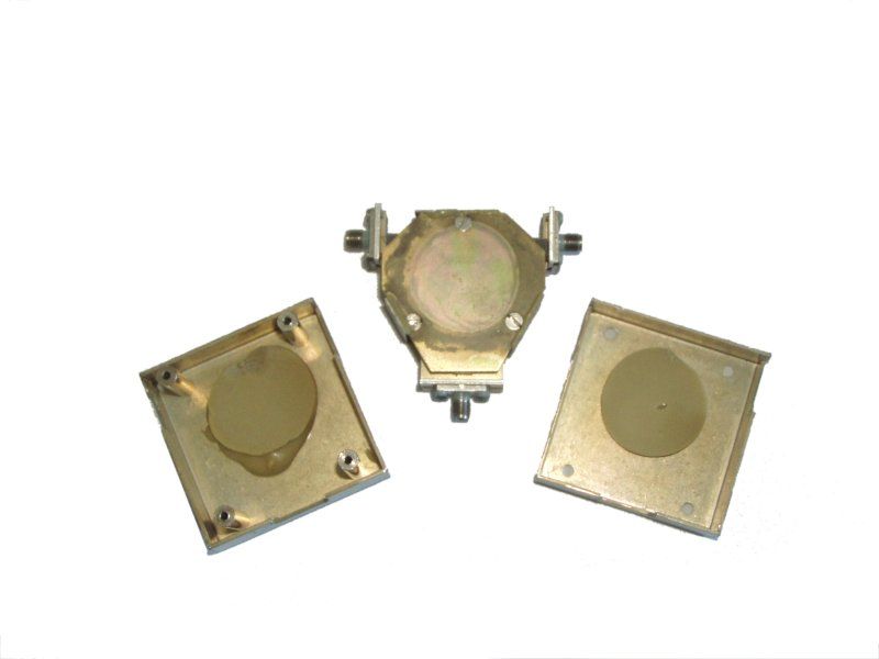
- Wikimedia Commons file page: Ferritzirkulator2.jpg (Averse), CC BY-SA licensing details.
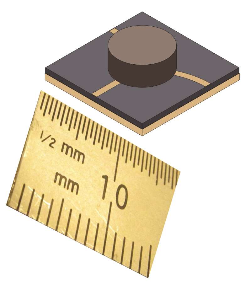
- Wikimedia Commons file page: Microstrip Circulator a.jpg (Dlinkhart), CC BY-SA 4.0 licensing details.
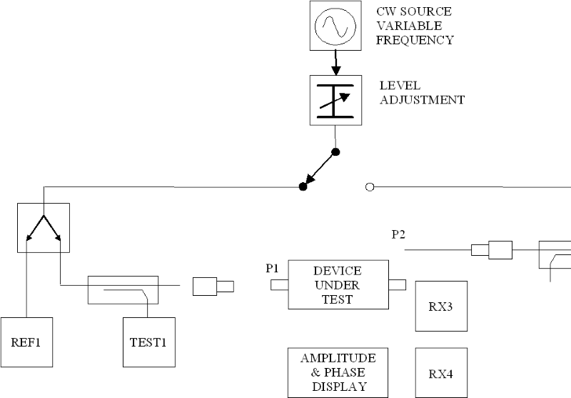
- Wikimedia Commons file page: Vector network analyzer.PNG (public domain).
- USGS media page: Deep Space Network antennas at Goldstone (public domain; credit NASA/JPL-Caltech).
- Pozar, D. M., Microwave Engineering, Wiley (for general microwave network and ferrite device fundamentals).
- IEEE Microwave Theory and Techniques Society (MTT-S) literature on ferrite devices and non-reciprocal components (for deeper theory and device variants).
Recommended Products

.jpg)


Keith Wong
Marketing Director, Chengdu Hertz Electronic Technology Co., Ltd. (Hzbeat)
Keith has over 18 years in the RF components industry, focusing on the intersection of technology, healthcare applications, and global market trends.