3-Port vs 4-Port RF Circulators
Discover the differences between 3-port and 4-port RF circulators. Learn how their structures, performance, and applications vary in radar, 5G, and satellite systems.
In the realm of RF and microwave engineering, circulators are the silent sentinels that manage the direction of power flow, ensuring systems remain stable, efficient, and protected. Among them, the 3-port and 4-port RF circulators stand as two major configurations, each serving unique design goals and application needs. But what truly sets them apart?
Operating Principle
Both 3-port and 4-port RF circulators operate on the same foundation: ferrite non-reciprocity under a static magnetic bias. This non-reciprocity allows energy to flow in one direction around the device, while the reverse path is strongly attenuated. The result—an elegant rotation of power between ports that maintains isolation and stability.
In a 3-port circulator, energy typically circulates from Port-1 → Port-2 → Port-3 → back to Port-1. The 4-port version extends this concept, forming a complete cycle of Port-1 → Port-2 → Port-3 → Port-4 → Port-1. This additional port enables more advanced routing topologies in complex microwave systems.
Structural Differences
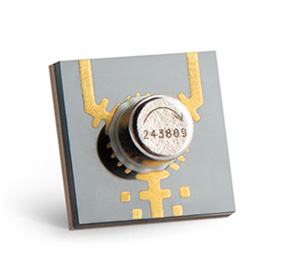
The 3-port circulator is typically built on a single ferrite disc or puck integrated with three microstrip junctions. This simplicity makes it compact, low-loss, and ideal for duplexing between transmitter and receiver chains.
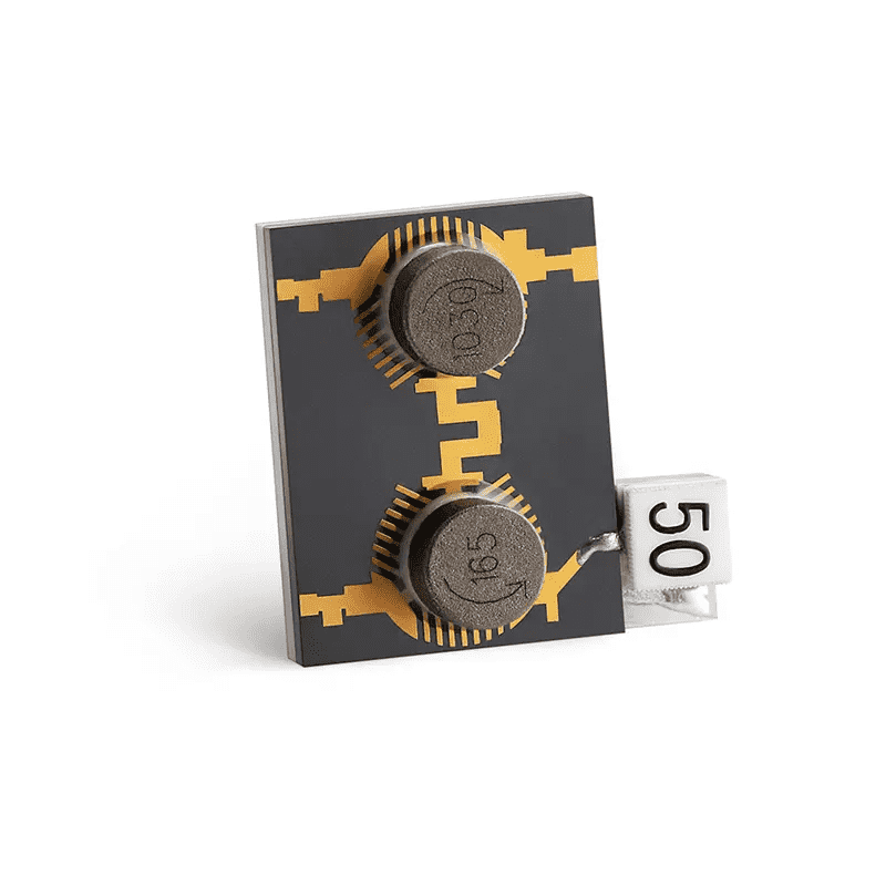
By contrast, the 4-port design typically consists of two ferrite elements magnetically coupled or stacked in a hybrid structure. Each ferrite handles a portion of the electromagnetic field, allowing signal flow through an additional path. This makes the 4-port circulator an excellent fit for signal combining, monitoring, or multi-antenna systems.
Performance Comparison
| Parameter | 3-Port Circulator | 4-Port Circulator |
|---|---|---|
| Typical Insertion Loss | < 0.3 dB | < 0.4 dB |
| Isolation | 20–25 dB | 25–30 dB |
| Size | Compact | Larger (Dual Core) |
| Function | Duplexing / Protection | Combining / Routing / Sensing |
| Applications | Base Stations, Radar Front-Ends | Multi-Channel Radar, Power Combining Networks |
Applications in Modern RF Systems
In modern RF engineering, the choice between 3-port and 4-port circulators depends on system complexity:
- 3-Port Circulators — ideal for transceiver isolation, ensuring the transmitter’s power does not reflect into the receiver path.
- 4-Port Circulators — enable multi-signal distribution or monitoring paths, commonly used in radar calibration networks, satellite feeder systems, and phased-array modules.
HzBeat’s advanced ferrite circulators are available in microstrip, drop-in, coaxial, and waveguide forms, covering frequencies from 20 MHz to 200 GHz, offering both standard and customized configurations to meet demanding RF system requirements.
FAQ
Q1: Can a 4-port circulator replace two 3-port ones?
Yes. In many cases, a 4-port design functions as a dual 3-port structure, simplifying integration and saving board space.
Q2: Which type offers better isolation?
The 4-port version generally achieves slightly higher isolation because of its dual magnetic path configuration.
Q3: Are they both non-reciprocal devices?
Yes. Both rely on ferrite non-reciprocity under magnetic bias and exhibit unidirectional signal flow.
References
- IEEE Transactions on Microwave Theory and Techniques
- NASA Technical Reports: Ferrite Non-Reciprocal Devices in Space Applications
- MDPI Electronics Journal – Ferrite Circulator Design Studies
- HzBeat RF & Microwave Components Product Data

Keith Wong
Marketing Director, Chengdu Hertz Electronic Technology Co., Ltd. (Hzbeat)
Keith has over 18 years in the RF components industry, focusing on the intersection of technology, healthcare applications, and global market trends.