RF Isolator vs RF Circulator: Which One to Use?
Compare RF isolator and RF circulator from an engineering perspective. Learn the key differences in function, structure, insertion loss, isolation, power handling, packaging, and how to select the right device for RF and microwave systems.
In microwave engineering, the difference between an RF isolator and an RF circulator looks simple on paper but becomes decisive in real hardware. One protects an amplifier from reflected power. The other lets a transmitter and receiver share a common antenna. Both are non-reciprocal ferrite devices. Both influence insertion loss, isolation, bandwidth, power handling, and system architecture. Yet they are not interchangeable in the way many purchasing lists, block diagrams, and even some lab notes casually assume.
This article explains the real engineering difference between an RF isolator and an RF circulator, how a microwave isolator is derived from a circulator topology, what a ferrite circulator is actually doing inside the package, and how to choose the right device for radar, communications, satellite links, test systems, power amplifiers, and compact front ends. If your design question is not merely “What are they?” but “Which one should I use, and what will it cost me in performance and packaging?” then you are exactly where you need to be.
.jpg)
Introduction: Why This Comparison Matters
In RF and microwave systems, the difference between an RF isolator and an RF circulator is not merely structural. It directly affects amplifier protection, antenna-path design, reflected-power control, receiver safety, and overall system stability. Although both devices are non-reciprocal ferrite components, they are intended for different signal-flow tasks and should not be selected as if they were interchangeable.
An RF isolator is typically used to maintain forward transmission while suppressing reverse power, making it a common choice for protecting power amplifiers, oscillators, and other sensitive active stages. An RF circulator, by contrast, is used to route RF energy among multiple ports in a defined sequence, which makes it especially valuable in shared-antenna architectures such as radar front ends, transceiver modules, and satellite communication systems.
The confusion often comes from the fact that a microwave isolator can be realized from a circulator topology with a matched termination. That relationship is technically correct, but it does not mean the two devices serve the same role in practice. A dedicated RF isolator is optimized for reverse-power absorption and source protection, while a dedicated ferrite circulator is optimized for controlled signal routing among three active ports. In real RF design, that distinction influences not only the schematic, but also insertion loss, isolation, package selection, thermal behavior, and long-term reliability.
What Is the Fundamental Difference?
RF Circulator: Three-Port Directional Routing
An RF circulator is a passive non-reciprocal device, most commonly implemented as a three-port ferrite-based component. Its defining function is circulation. If RF power enters Port 1, it exits Port 2. If power enters Port 2, it exits Port 3. If power enters Port 3, it exits Port 1. That controlled rotation of energy is what makes the ferrite circulator valuable in duplexing, T/R modules, antenna-sharing architectures, and radar front ends.
RF Isolator: Two-Port Forward Transmission with Reverse Protection
An RF isolator is a two-port non-reciprocal device. It allows forward power to pass with low insertion loss, but reverse power is heavily attenuated and typically dissipated in an internal termination. In a practical system, the microwave isolator sits between a source and a load to keep reflections from traveling backward into a transistor, amplifier, oscillator, mixer chain, or sensitive measurement port.
The Relationship Between Them
The most important conceptual bridge is this: an isolator is often a special case of a circulator. Terminate one port of a three-port RF circulator with a matched load and the remaining two ports behave like an RF isolator.
| Parameter | RF Isolator | RF Circulator |
|---|---|---|
| Port count | 2 ports | Usually 3 ports |
| Main function | One-way transmission and reverse isolation | Sequential routing among ports |
| Typical use | Protect amplifier, oscillator, or source from reflected power | Share one antenna between TX and RX; route signals in duplex systems |
| Internal concept | Often derived from a circulator plus matched termination | Ferrite-based non-reciprocal junction or transmission structure |
| Best fit | Protection and stability | Routing and architecture flexibility |
How Do These Devices Actually Work?
The physics behind the RF isolator and RF circulator comes from non-reciprocity in magnetically biased ferrite materials. In simple language, a ferrite under magnetic bias does not present the same electromagnetic behavior to waves traveling in opposite rotational senses. That asymmetry lets the device favor one signal path and suppress another. The result is not magic. It is disciplined electromagnetic biasing, ferrite material selection, junction geometry, matching design, and packaging.
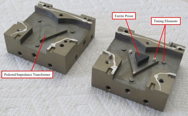
In a waveguide ferrite circulator, for example, a ferrite post is often placed at the center of a three-way junction, and a static bias field is supplied by magnets. Dielectric tuning elements or matching structures are used to reduce reflection and shape the desired transmission path. In planar devices such as microstrip parts, multiple material layers, magnetic structures, and transmission patterns are combined to realize similar behavior in a much smaller footprint.
The important engineering point is not merely that ferrite causes non-reciprocity, but that the usable region sits between bad extremes. If the device is biased at the wrong condition, insertion loss rises. If the magnetic domains are not properly aligned, loss also rises. So the useful RF circulator is always a product of careful bias control, matching control, and manufacturing discipline. The same is true for the microwave isolator, particularly when high power and broad operating temperature are involved.
When Should You Use an RF Isolator?
Choose an RF isolator when the main engineering problem is reverse energy. That is the cleanest rule. If your amplifier, driver stage, oscillator, synthesizer, or source sees an unpredictable load and may suffer from reflected power, a microwave isolator is usually the correct answer.
- Power amplifier protection: The classic use of an RF isolator is to protect a PA from load mismatch. Reverse power can alter gain, create instability, increase stress, and shorten device life.
- Oscillator stability: Sensitive oscillators do not enjoy seeing their own reflections returning from downstream circuitry. An RF isolator helps preserve frequency stability and phase behavior.
- Measurement setups: In test benches, a microwave isolator can reduce the effect of mismatch between source, DUT, and instrument ports.
- Compact signal chains: If you only need two active ports and do not need antenna-sharing circulation, an RF isolator is simpler, cleaner, and often more space-efficient.
In other words, the RF isolator is the bodyguard. It stands between your expensive active device and the chaos of the real world. If your system does not need three-port routing, adding an RF circulator can be like bringing a traffic circle to a one-lane road: technically possible, operationally unnecessary.
When Should You Use an RF Circulator?
Choose an RF circulator when the engineering problem is signal routing between three functional nodes. The most common example is transmitter, antenna, and receiver sharing a common antenna path. In that architecture, the ferrite circulator is not just protecting a source; it is enabling the whole topology.
- Radar front ends: A transmitter pulse can be sent from one port to the antenna while received echoes returning from the antenna are directed to the receiver port.
- T/R modules and phased arrays: The RF circulator supports compact routing and antenna sharing in systems where space, mass, and channel density matter.
- Satellite communications: Shared-path microwave architectures frequently rely on circulators to control forward and reverse energy paths.
- Full-duplex or quasi-duplex microwave chains: If you must direct different energy flows to different ports, the RF circulator is the more natural device.
A practical design choice often comes down to this: if you are asking “How do I keep the reverse wave away from the source?” you probably need an RF isolator. If you are asking “How do I send forward power one way and returning energy somewhere else useful?” you probably need an RF circulator.

Performance Metrics That Decide the Winner
Whether you are choosing an RF isolator or an RF circulator, the key metrics are not mysterious. They are the same unforgiving numbers every microwave engineer knows and respects.
1. Insertion Loss
Lower insertion loss preserves more forward power. In a receiver chain, it protects noise figure. In a power path, it preserves efficiency and reduces thermal burden. A microwave isolator with poor insertion loss may protect the amplifier while quietly punishing the whole link budget. Likewise, an RF circulator with excessive insertion loss may make a shared-antenna architecture look elegant on the schematic and disappointing on the bench.
2. Isolation
Isolation tells you how effectively the unwanted path is suppressed. For an RF isolator, this is reverse isolation. For an RF circulator, this is the suppression of the non-adjacent or undesired path. If your system is exposed to high reflected power, adjacent-channel leakage, or receiver vulnerability, isolation is not a brochure number. It is a survival number.
3. VSWR / Return Loss
Matching matters because mismatch creates the very reflections these devices are meant to control. If the part itself presents a poor match, you can lose some of the benefit at the system level. This is why a purpose-built RF isolator may outperform a casual “circulator plus load” workaround.
4. Bandwidth
Ferrite devices are not infinitely broadband by nature. Device geometry, matching structures, ferrite properties, and package implementation all shape usable bandwidth. Microstrip parts can offer attractive size advantages, but broader bandwidth often comes with careful compromise rather than free lunch.
5. Power Handling and Thermal Design
A high-power RF circulator and a high-power RF isolator must both handle internal fields, thermal rise, and package stress. In the isolator, the termination handling reverse power becomes critical. In the circulator, ferrite, housing, junction dimensions, and connector or waveguide structure drive the ceiling.
6. Size, Weight, and Integration Style
Coaxial, drop-in, SMT, microstrip, and waveguide versions all exist. The smaller you go, the more disciplined your trade space becomes. Compact devices are excellent for integration, but miniaturization often narrows room for error in bandwidth, isolation, and power dissipation.
Packaging Matters More Than People Admit
An RF isolator or RF circulator is not just a function. It is a package choice. That package determines how the part lives in your system.
- Coaxial: Common in general RF and microwave assemblies, easy to integrate with cable and connectorized hardware.
- Waveguide: Favored in higher-power and certain high-frequency systems where low loss and robust structure matter.
- Drop-in / SMT / microstrip: Ideal for compact platforms, phased arrays, avionics, and miniaturized assemblies where volume and mass are tightly controlled.
This is where the selection discussion becomes practical. A waveguide ferrite circulator may be ideal for power and low loss, while a planar microwave isolator may be ideal for compact integration inside an RF module. Engineers who compare parts only by center frequency and isolation are buying a violin based on string count. The music comes later, and usually with regret.
How to Decide: A Practical Selection Framework
Use the following decision logic when choosing between an RF isolator and an RF circulator:
- Define the function first. Do you need protection only, or routing among three active ports?
- Map the power flow. Where should forward power go? Where should reverse power go?
- Check system sensitivity. Is the source vulnerable to reflection, oscillation pulling, or damage?
- Check antenna-sharing needs. If TX and RX must share a common path, an RF circulator is often the right architecture.
- Evaluate package constraints. Coaxial, waveguide, microstrip, drop-in, and SMT each imply different integration costs.
- Review real metrics. Insertion loss, isolation, VSWR, bandwidth, power handling, and temperature range all matter.
- Do not forget the load. In an RF isolator, absorbed reverse power becomes heat. That heat is not theoretical. It must go somewhere.
| If your priority is... | Best choice | Why |
|---|---|---|
| Protecting a PA or oscillator from reflections | RF isolator | It is purpose-built for one-way transmission and reverse-energy suppression |
| Sharing one antenna between TX and RX | RF circulator | It routes energy among three ports in sequence |
| Compact two-port module protection | Microwave isolator | Simpler architecture, fewer active routing requirements |
| Radar or T/R module routing | Ferrite circulator | Supports directional separation of transmit and receive paths |
| Minimal complexity where no third port is needed | RF isolator | Do not pay for routing you do not need |
Common Selection Mistakes
The first mistake is assuming that an RF isolator and an RF circulator are interchangeable because one can be derived from the other. In principle, yes. In practical system design, not always.
The second mistake is ignoring absorbed reverse power. A microwave isolator does not erase reflected energy; it redirects and dissipates it. That means load capability and thermal path matter.
The third mistake is underestimating packaging. A small SMT device may fit beautifully while creating new pain in power handling and heat. A waveguide ferrite circulator may look mechanically bulky but save a high-power design from ugly compromises.
The fourth mistake is shopping by headline specs only. Isolation at one frequency point does not tell you the whole story across bandwidth, temperature, mismatch, or power.
Conclusion
The question “RF isolator vs RF circulator: which one to use?” has a clean answer once the signal-flow objective is honest. Use an RF isolator when you need forward transmission with reverse protection. Use an RF circulator when you need controlled routing among three ports. A microwave isolator is the guardian of source stability. A ferrite circulator is the traffic controller of shared-path microwave architecture.
In advanced RF systems, this is not a semantic distinction. It affects amplifier reliability, receiver safety, duplexing strategy, antenna-sharing efficiency, thermal design, module size, and total system cost. The best choice is the one whose physics, topology, and packaging align with the actual power-flow problem in front of you.
In short: if you need protection, choose the RF isolator. If you need routing, choose the RF circulator. If you choose blindly, the lab will educate you with unusual speed and zero mercy.
FAQ
1. Is an RF isolator just an RF circulator with a load?
Conceptually, yes. A two-port RF isolator can be realized by terminating one port of a three-port RF circulator with a matched load. However, a purpose-built isolator may be optimized for better matching, thermal handling, and reverse absorption than a generic circulator-plus-load solution.
2. Which is better for a power amplifier, an RF isolator or an RF circulator?
In most cases, an RF isolator is the better choice for protecting a power amplifier from reflected power. If you also need to route signals among transmitter, antenna, and receiver, then an RF circulator may be the correct architecture.
3. Why are ferrite materials used in these devices?
Ferrite materials enable the non-reciprocal behavior needed for one-way isolation and controlled circulation when they are properly magnetically biased. That is why the classic ferrite circulator remains fundamental in microwave hardware.
4. Are microwave isolators and circulators broadband?
They can be designed for useful bandwidths, but bandwidth is never free. It depends on ferrite properties, junction design, matching structures, and package type. A microwave isolator or RF circulator must always be evaluated over the actual operating band, not just at center frequency.
5. What parameters should I compare first?
Start with insertion loss, isolation, VSWR, frequency range, power handling, package style, and operating temperature. For an RF isolator, termination and thermal dissipation are especially important. For an RF circulator, port routing behavior and non-adjacent isolation are critical.
6. Can an RF circulator replace a duplexer?
In some architectures, yes, especially where transmitter and receiver share a common antenna path. But the answer depends on power, leakage, bandwidth, selectivity requirements, and system topology. A circulator handles directional routing; a duplexer or filter network handles frequency selectivity.
References
- Smiths Interconnect, The anatomy of a microstrip isolator and circulator.
- Pasternack Blog, What are RF Isolators and RF Circulators?.
- Pasternack Blog, The Importance of Coax Isolators in RF System Performance.
- COMSOL, Three-Port Ferrite Circulator.
- RF Circulator Inc., Operating Principle of Junction Circulators.
- everything RF, What are Ferrite Devices?.
- Wikimedia Commons, Waveguide collection.
- Wikimedia Commons, WR-112 Circulator with Bullets.
- Wikimedia Commons, Microwave Microsystems Laboratory.
Recommended Products

.jpg)


Keith Wong
Marketing Director, Chengdu Hertz Electronic Technology Co., Ltd. (Hzbeat)
Keith has over 18 years in the RF components industry, focusing on the intersection of technology, healthcare applications, and global market trends.