Which Type of RF Circulator Fits Your Design?
A practical RF circulator selection guide: microstrip, drop-in, waveguide, and SMT/SMD options compared. Learn how to match isolation, insertion loss, bandwidth, power, VSWR, and size to S-, C-, X-, Ku-, and Ka-band designs.
Choosing the right RF circulator means aligning band, bandwidth, isolation, insertion loss, power handling, VSWR, temperature, size, and cost. This guide compares microstrip, drop-in, waveguide, and SMT/SMD circulators and shows how to pick the best fit for S-/C-/X-/Ku-/Ka-band applications, phased arrays, 5G small cells, SATCOM, and radar front-ends.
1. Circulator Types at a Glance
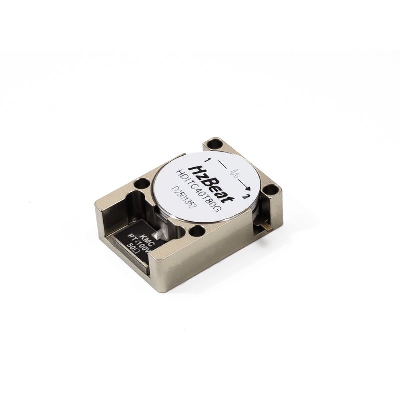
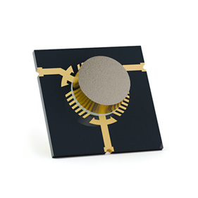
- Microstrip/SMT — Planar, lightweight, excellent for broadband designs and compact arrays.
- Drop-in — Machined cavity; strong thermal path and power handling.
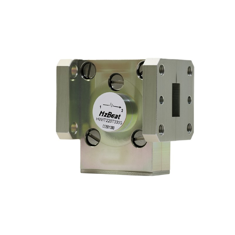
- Waveguide — Ultra-low IL and very high power, ideal for Ku/Ka SATCOM and radar.
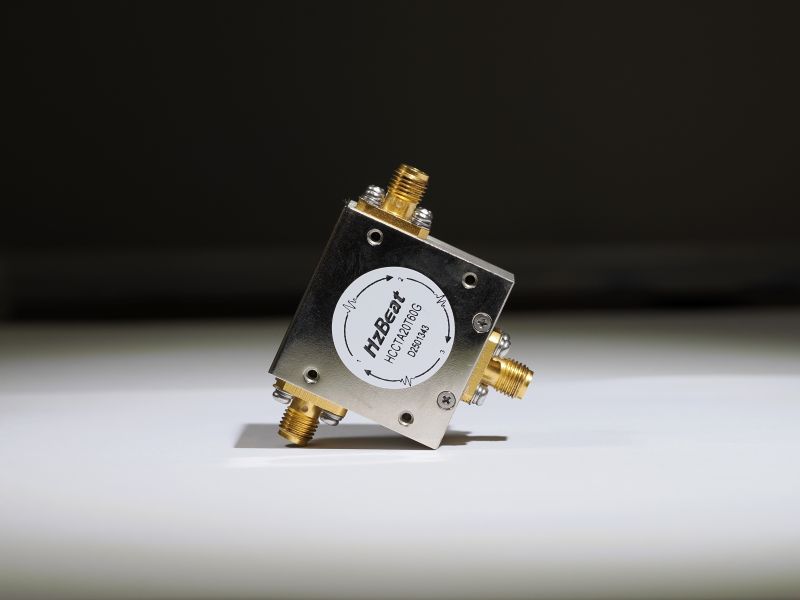
- Coaxial — Convenient RF connectors for benchtop and rack integrations; easy swap/testing.
2. The Five Specs That Decide Your Choice
2.1 Insertion Loss (IL)
Lower IL preserves link margin; waveguide best at high frequency, drop-in/microstrip competitive in S-/C-/X-band; SMT trades tiny size for slightly higher IL.
2.2 Isolation (ISO)
Target ≥ 20–23 dB baseline; ≥ 25–28 dB for radar/T/R modules. Validate over temperature and bandwidth.
2.3 VSWR
VSWR ≤ 1.25:1 is excellent; ≤ 1.5:1 is common for wideband designs.
2.4 Bandwidth
Microstrip enables octave-class bandwidth; waveguide/drop-in excel for high-Q windows with superior IL/ISO.
2.5 Power & Thermal
Define average/peak/duty/pulse. Drop-in and waveguide offer better thermal paths for high power.
3. Selection Matrix: Microstrip vs Drop-In vs Waveguide vs SMT
| Type | Best For | IL | ISO | Power | Bandwidth | Form |
|---|---|---|---|---|---|---|
| Microstrip/SMT | Broadband arrays; small cells | Med–Low | Med | Low–Med | Wide | PCB/SMT |
| Drop-In | Rugged radios; HP links | Low | High | High | Med | Machined cavity |
| Waveguide | Ku/Ka SATCOM; radar | Very low | High | Very high | Narrow–Med | WG ports |
| Coaxial | Test/rack systems | Low | High | Med | Med | SMA/K-type |
4. Band-by-Band Guidance
S-band (2–4 GHz): microstrip or drop-in; C-band (4–8): drop-in/waveguide for power; X-band (8–12): waveguide for low IL; Ku/Ka (12–40): waveguide dominates power and loss, microstrip possible with careful stack-up.
5. Use-Case Playbook
- Phased array TRMs: microstrip/SMT for density; validate ISO vs temperature.
- 5G small cells: SMT for BOM/assembly; ensure reflow survivability.
- High-power links/pulsed radar: drop-in or waveguide; request derating curves.
- SATCOM earth stations: minimize IL; waveguide in Ku/Ka.
6. Integration & Test Tips
- Bias magnet & ferrite: request temperature coefficients when ISO is critical across -40…+85 °C.
- Thermal path: heatsink tie for drop-in/waveguide; thermal vias under microstrip/SMT.
- Launches: simulate transitions; treat launches as part of the match.
- Bench: verify forward loss, reverse ISO, return loss on all three ports.
- Reliability: shock/vibe, moisture sensitivity (SMT), outgassing (space).
7. FAQ
Q1. What’s the fastest way to narrow the choice?
Start with band + bandwidth + power, then refine by IL/ISO/VSWR and mechanics.
Q2. How much isolation is “enough”?
≥ 20–23 dB for many radios; ≥ 25–28 dB for radar or delicate HPAs.
Q3. Can an SMT circulator replace a drop-in?
For low/medium power—verify thermal rise, IL, ISO in-situ. For pulsed high-power, use drop-in or waveguide.
Q4. Useful long-tail terms
low insertion loss microstrip circulator, Ka-band waveguide circulator, high-isolation drop-in circulator VSWR 1.3:1, SMT circulator reflow compatible.
Recommended Products

.jpg)


Keith Wong
Marketing Director, Chengdu Hertz Electronic Technology Co., Ltd. (Hzbeat)
Keith has over 18 years in the RF components industry, focusing on the intersection of technology, healthcare applications, and global market trends.