Where Should an RF Isolator Be Placed in an RF System?
Learn where to place an RF isolator in an RF system, including amplifier outputs, antenna paths, signal sources, test benches, and cascaded amplifier stages.
In many RF systems, the question is not only whether an RF isolator is needed, but where it should be placed. A correctly placed isolator can protect a power amplifier, stabilize a signal source, reduce mismatch sensitivity, and improve measurement repeatability. A poorly placed one, however, may add insertion loss without solving the real reflection problem.
The most common answer is simple: place the RF isolator as close as practical to the component that must be protected from reflected power. In transmit chains, that usually means between the power amplifier and the antenna, load, filter, switch, or external port. In test benches, it may sit between a signal source and the device under test, or between a booster amplifier and a reflective fixture. In multi-stage RF designs, isolators may also be used between amplifier stages to prevent one stage from disturbing another.
Why RF Isolator Placement Matters
RF systems are designed around impedance, power, frequency, and stability. On paper, many components are specified in a clean 50-ohm environment. Real systems are less polite. Antennas detune, cables age, filters reflect outside their passband, switches introduce state-dependent mismatch, and devices under test can look very different from a perfect load.
When a load is mismatched, part of the forward signal returns toward the source. That reflected energy can raise voltage or current stress, disturb gain flatness, change phase behavior, heat the output stage, or push an amplifier into unstable operation. Analog Devices notes that poor return loss and arbitrary phase at RF ports can affect insertion loss, isolation, and power handling, and that reactive loads may cause voltage or current peaking beyond device limits.
This is where RF isolator placement becomes a system-level decision. The isolator should sit where it can intercept reverse energy before the protected device sees it. In other words, do not only ask “What isolation value do I need?” Ask “Where will the reflected power travel, and what component should never see it?”
This basic order is the backbone of many transmitter chains: the amplifier drives forward power through the isolator, while reflected power from the antenna side is absorbed by the isolator load instead of returning to the amplifier.
The Most Common Position: Between the Power Amplifier and Antenna
The most common RF isolator placement is at the output of a power amplifier, before the antenna feed, filter, switch matrix, waveguide run, or external connector. This position is especially important when the load impedance may change during operation.
Examples include mobile base stations exposed to weather and antenna movement, radar transmitters operating with pulsed high power, satellite uplinks connected to long outdoor feed systems, and laboratory amplifiers used with unknown or changing devices under test. In all of these cases, the amplifier is valuable, heat-sensitive, and often operating close to its rated output. It deserves a one-way gate.
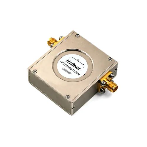
Pasternack describes RF isolators as passive two-port microwave devices that help protect RF components from excessive current or signal reflection. EMR also explains the classic transmitter-to-antenna arrangement: forward RF power travels toward the antenna with low loss, while reflected energy from mismatch or detuning is directed toward the termination rather than the transmitter power amplifier.
Why the Isolator Usually Goes After the Amplifier
If the isolator is placed before the power amplifier, it may protect the signal source, but it will not protect the amplifier output from antenna mismatch. The reflected energy from the antenna still travels back into the PA output. For PA protection, the isolator belongs downstream of the PA.
For compact RF front ends, this can become a mechanical packaging challenge. Engineers need enough spacing for connectors, heat dissipation, grounding, and service access. In high-power systems, the termination inside the isolator must also be rated for realistic reverse-power events. A beautiful placement on the schematic can still fail if the load cannot dissipate the heat.
When to Place an RF Isolator After a Signal Source
Signal generators, oscillators, synthesizers, and local oscillator chains can be sensitive to load pulling. A poor load may shift frequency, change output amplitude, increase spurious behavior, or make repeatable measurements difficult. In this case, the isolator may be placed directly after the source.
RF-CI describes this as decoupling of generators and loads: connecting an isolator to the generator can attenuate the reflected signal by the amount of its isolation, helping minimize frequency shift and improve generator stability. This is a different use case from PA output protection, but the logic is the same: isolate the sensitive source from whatever happens downstream.
This placement is useful in test systems where a signal generator feeds a mixer, amplifier, switch matrix, antenna port, or prototype board with uncertain match. It is also useful in production test, where many units with slightly different impedance behavior are connected to the same source over and over again. The isolator helps the test source see a more consistent environment.
Source-Side Placement Is Not a Substitute for PA Protection
One common mistake is assuming that an isolator at the source protects the entire RF chain. It does not. It mainly protects or stabilizes the source. If a downstream power amplifier faces severe load mismatch, the PA output may still need its own isolator. In high-value systems, it is not unusual to use isolators at more than one point because the protected component changes from section to section.
RF Isolators Between Cascaded Amplifier Stages
In multi-stage amplifier chains, one stage can interact with the next through imperfect matching, reverse leakage, and changing operating conditions. Placing an isolator between amplifier stages can improve interstage matching and reduce the chance that one stage disturbs another.
RF-CI specifically identifies isolators as commonly used for decoupling cascaded amplifier stages. In that role, the isolator between stages provides an interstage matching network and protects an amplifier from reverse power if another stage fails. This is a quiet but important use case: the isolator becomes a shock absorber between active devices.
| Placement Point | Main Purpose | Typical Risk Controlled | Common Products |
|---|---|---|---|
| PA output to antenna path | Protect the amplifier from reflected power | Antenna mismatch, cable detuning, open/shorted load | High-power coaxial isolator, high-power waveguide isolator |
| After signal generator or oscillator | Stabilize source behavior | Load pulling, frequency shift, amplitude variation | Coaxial isolator, drop-in isolator |
| Between amplifier stages | Improve stage-to-stage decoupling | Reverse interaction, instability, failure propagation | Drop-in isolator, microstrip isolator |
| High-power test bench | Protect instruments and improve repeatability | Reflective DUTs, compression, receiver damage | Coaxial isolator, waveguide isolator, high-power load |
RF Isolator Placement in Test and Measurement Setups
Test benches are often more chaotic than final products. One day the bench measures a well-matched filter; the next day it drives a prototype antenna, a saturated PA, a switch network, or a device under test with unknown impedance. This makes RF isolators valuable in measurement systems.
In a VNA or signal generator setup, an isolator can help reduce the effect of DUT reflections on the source. In a high-power amplifier test, an isolator and appropriate attenuation can help protect instruments from reverse power. Keysight notes that high-power PA characterization often requires booster amplifiers and that high power levels can risk damaging network analyzer hardware if the receiver path is not protected correctly.
Typical Test Bench Positions
- Between signal generator and DUT: improves source stability when DUT impedance changes.
- Between booster amplifier and DUT: helps prevent reflected power from returning to the booster amplifier.
- Before sensitive receiver paths: used with couplers, attenuators, limiters, and terminations to control exposure to high power.
- Inside production fixtures: improves repeatability when many units are tested under the same setup.
The isolator is not the only protection element. High-power attenuators, directional couplers, limiters, loads, interlocks, and correct calibration planes all matter. But the isolator is often the part that makes the source or amplifier feel like the rest of the bench is less unpredictable.
Coaxial, Drop-in, Microstrip, and Waveguide Placement Differences
The correct placement also depends on the isolator package. A coaxial RF isolator is often the easiest to insert into a connectorized chain. It is common in lab setups, base stations, repeaters, broadcast transmitters, and modular RF equipment. Its advantage is practical deployment: plug it into the line, define direction, verify power rating, and manage heat.
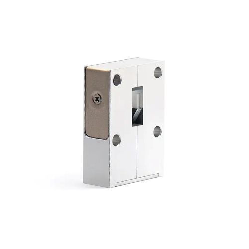
A drop-in isolator is more often used inside an RF module where the mechanical layout, cavity, grounding, and thermal path are controlled by the equipment designer. It is not simply “placed in a cable”; it is integrated into the internal RF path. For this reason, its placement should be considered early in the RF layout, not after the enclosure is already frozen.
A microstrip isolator or SMT-style isolator fits dense PCB and front-end module designs. Here, placement is closely tied to board-level routing, ground continuity, magnetic bias clearance, soldering process, and nearby thermal sources. The isolator should be close enough to protect the active stage but not so cramped that grounding, solderability, or magnetic performance is compromised.
A waveguide isolator belongs in high-frequency or high-power waveguide paths, especially where very low insertion loss and high power handling are required. Waveguide placement is dominated by flange orientation, mechanical support, cooling, and the available space around the load port.
Common RF Isolator Placement Mistakes to Avoid
Installing the Isolator Backwards
Direction matters. An isolator installed in the wrong direction can block the intended forward path and fail to protect the component it was selected for.
Protecting the Wrong Component
An isolator after the source does not automatically protect the PA output. Place it according to the reflected-power path.
Ignoring the Load Rating
Isolation only helps if the internal or external termination can absorb the expected reverse power without overheating.
Forgetting Insertion Loss
Low insertion loss is critical near the PA output because every fraction of a dB can become heat, lost link budget, or reduced efficiency.
Another mistake is treating isolation as a fixed number without considering the match of the other ports. RF-CI notes that isolation can be affected by termination VSWR. In real designs, the isolator, the load, the cable, and the surrounding network all shape the final protection level.
How to Choose the Right RF Isolator for Your System
Once the placement is clear, the selection process becomes more concrete. Start with the protected component and the expected reflection scenario. Then define frequency band, bandwidth, forward power, peak power, reverse power, insertion loss, isolation, VSWR, package type, mounting method, connector or flange interface, temperature range, and available space.
For HzBeat projects, a practical RFQ should include the operating frequency range, required bandwidth, CW and peak power, estimated reflected power, required isolation, maximum insertion loss, port direction, connector or flange type, mechanical drawing constraints, operating temperature, and whether the isolator will sit after a PA, after a signal source, between stages, or in a test system.
HzBeat provides RF isolator solutions across microstrip, drop-in, coaxial, and waveguide platforms, including high-power and customized designs. For placement-sensitive projects, the best design conversation often begins with a simple system sketch: source, amplifier, filter, switch, antenna or load, expected reflected power, and available mounting space.
Conclusion
An RF isolator should be placed where it can stop reverse energy before that energy reaches the component you need to protect. For most transmit systems, that means placing the isolator after the power amplifier and before the antenna-side network. For signal-source stability, it may sit immediately after the generator or oscillator. For cascaded amplifier chains, it can sit between stages. For test benches, it is often used near sources, booster amplifiers, or sensitive measurement paths.
The best placement is not a universal point on a schematic. It is a decision based on reflection paths, power levels, impedance uncertainty, thermal limits, and the value of the component at risk. Put simply: follow the reflected power, find the vulnerable device, and place the isolator before trouble gets there.
FAQ
Should an RF isolator be placed before or after a power amplifier?
For amplifier protection, the RF isolator is usually placed after the power amplifier, between the PA output and the antenna, load, filter, or external RF port. This position helps absorb reflected energy before it returns to the amplifier.
Can an RF isolator protect an amplifier from antenna mismatch?
Yes, this is one of the most common reasons to use an RF isolator. When an antenna becomes mismatched or detuned, reflected power can travel back toward the PA. A correctly placed isolator redirects much of that reverse energy into its termination.
Can I place an RF isolator after a signal generator?
Yes. Placing an isolator after a signal generator or oscillator can reduce the effect of load reflections on the source, improving frequency stability, amplitude consistency, and measurement repeatability.
Do cascaded amplifiers need RF isolators between stages?
Not always, but interstage isolators are useful when reverse interaction, mismatch, or stage failure could affect system stability. They can improve interstage matching and reduce the chance that one amplifier stage disturbs another.
What happens if an RF isolator is installed backwards?
If installed backwards, the isolator may attenuate or block the intended forward signal path and fail to protect the target component. Always check the arrow, port marking, or datasheet direction before installation.
Does RF isolator placement affect insertion loss?
The isolator’s insertion loss is part of the forward path wherever it is installed. Placement near a PA output or in a low-noise path should be evaluated carefully because even small insertion loss can affect efficiency, heat, or link budget.
References
- Pasternack, RF Isolators.
- RF Circulator Isolator, Inc., Applications of Ferrite Circulators and Isolators.
- EMR Corporation, The Care & Feeding of the R.F. Isolator.
- Analog Devices, AN-2558: RF Switch Performance with Arbitrary Loads.
- Keysight, High Power Amplifier Test Enhancements with the ENA-X VNA.
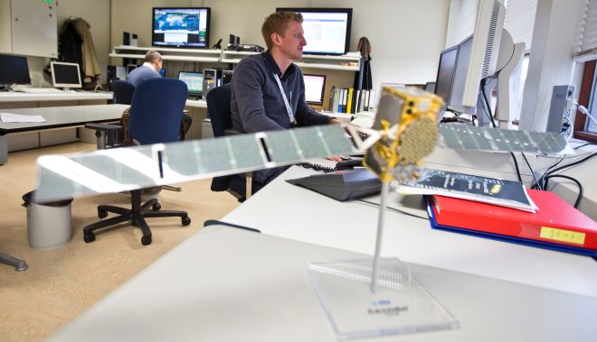
- ESA, Radio Frequency Systems, Payload and Technology Laboratories.
- HzBeat, RF Isolator Manufacturer: Microstrip, Drop-in, Coaxial & Waveguide RF Isolators.
- HzBeat, High Power Coaxial Isolator.
- HzBeat, High Power Waveguide Isolator.
Recommended Products

.jpg)


Keith Wong
Marketing Director, Chengdu Hertz Electronic Technology Co., Ltd. (Hzbeat)
Keith has over 18 years in the RF components industry, focusing on the intersection of technology, healthcare applications, and global market trends.