AI Meets RF: Where Will Electronic Component Demand Boom?
Updated on:
Keywords: AI accelerates demand for RF circulators and isolators, RF circulators, RF isolators, AI in circulators and isolators
AI is no longer just code; it is copper, ferrite and packaging. As training clusters scale and 6G takes shape, non‑reciprocal RF components—circulators and isolators—quietly safeguard links, tame reflections, and stabilize duplex operation across data centers, radar and satcom.
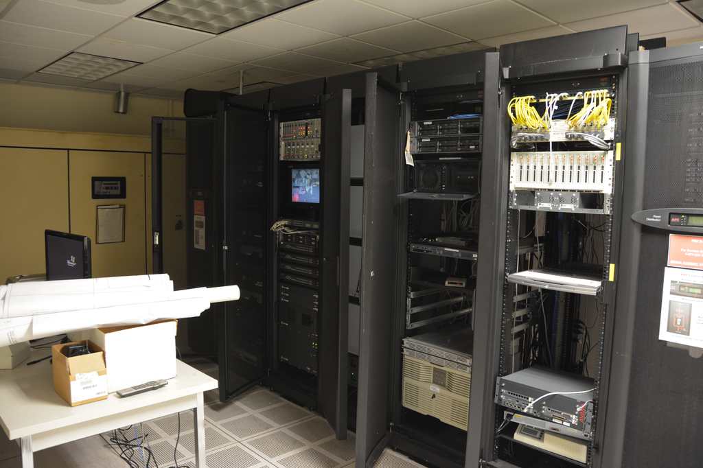
Cover — Server room racks (Carl Lender, CC BY 2.0, via Wikimedia Commons).
Market Momentum
Baseline RF markets are expanding on the back of 5G, consumer connectivity and radar/satellite modernization. According to Yole Group, the broader RF market is forecast to grow from about $51.3 billion (2024) to roughly $70 billion by 2030—a new era driven by integration and global competition. AI‑centric compute and sensing will amplify this baseline by demanding cleaner, wider‑band, and more power‑capable front‑ends.
Why RF Matters to Al
AI Data Centers6G / mmWaveIntelligent RadarSatcom
Data‑center fabrics. As link speeds climb, analog margins shrink. Isolators enforce one‑way protection for sensitive LNA/PA stages, absorb back‑reflections from dense cabling/optics, and stabilize duplex operation—key to maintaining signal integrity in AI racks.
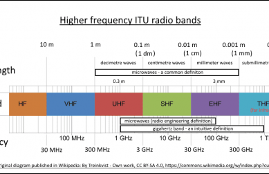
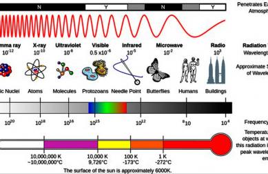
6G & Joint Communication‑Sensing (JCAS). Phased arrays and JCAS push radios to form many beams, reconfigure rapidly, and share spectrum with sensing. This lifts the bar for wideband, miniaturized non‑reciprocal elements that operate into mmWave and potentially sub‑THz.
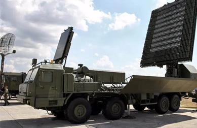
Intelligent radar & autonomy. AI‑assisted perception tightens RF budgets; higher transmit power and denser packaging demand better isolation to mitigate self‑interference and protect front‑ends.
Satcom & TT&C. Constellations and gateways require radiation‑tolerant, temperature‑stable circulators/isolators to secure long‑lived duplex links and one‑way protection in harsh environments.
Al Workloads Depend on RF Integrity
Algorithm–hardware interplay. Large-scale AI training relies on ultra-fast interconnects. When optical/electrical fabrics exceed 400G/800G per lane, even minor return loss or crosstalk can cut effective throughput and elongate training cycles. RF isolators and circulators directly influence link latency, jitter, and bit-error rate, which map onto model convergence time and energy efficiency.
Case study – AI racks. In GPU clusters, each percentage point of signal integrity loss can translate into hours of additional training for foundation models. Ensuring clean duplex paths with non-reciprocal components reduces packet retries and power draw, improving total cost of ownership (TCO) for hyperscale data centers.
System impact. Put simply: RF stability is not peripheral—it is a hidden factor shaping the economics of AI deployment at scale.
Al-Assisted RF Component Design
Materials discovery. Machine-learning models accelerate ferrite material optimization by predicting permeability, saturation magnetization, and loss tangent across compositions—shrinking experimental cycles from months to weeks.
Geometry & packaging. AI-driven electromagnetic solvers explore thousands of circulator/isolator layouts (microstrip, drop-in, coaxial, waveguide) to minimize insertion loss and maximize isolation under thermal stress. Surrogate models replace time-consuming full-wave simulations, enabling rapid iteration.
Adaptive control. Embedding AI algorithms into RF modules allows self-calibration and real-time health monitoring. Non-reciprocal devices can adjust bias fields or switch to redundant paths proactively—critical for satellites, defense radars, and high-uptime AI data centers.
Outlook. This feedback loop—AI workloads demanding better RF, and AI helping design smarter RF—marks a reinforcing cycle that will dominate the next decade of component innovation.
Demand Hot Zones
AI Data Centers
Ultra‑low loss + thermal stability for dense racks. Opportunities: compact non‑reciprocal modules co‑packaged with optics/high‑speed electrical links.
6G / mmWave
Phased‑array tiles need wideband, miniaturized isolators/circulators; joint comm‑sensing widens instantaneous bandwidths.
Intelligent Radar
Higher transmit power and tight form factors raise isolation requirements; ferrite selection and geometry become differentiators.
Satellite & TT&C
Radiation‑hardened, wide‑temperature devices for long‑duration reliability; waveguide or drop‑in variants for high power.
Technical Challenges
- Bandwidth vs Loss: Extending non‑reciprocity to mmWave/sub‑THz typically increases loss; careful ferrite properties, geometry and matching networks are essential.
- Thermal & Power: AI clusters raise power density; components must withstand higher junction temps and dissipate heat efficiently.
- Miniaturization: Pressure for smaller TR‑modules favors microstrip/SMT solutions and innovative drop‑in packaging.
- Integration pathways: Magnet‑less or time‑varying approaches are promising for on‑chip integration, but noise and linearity must be managed.
Strategy Playbook
- Tunable / self‑monitoring nodes: Pair non‑reciprocal devices with control loops for health metrics and adaptive response.
- Spec first: Prioritize insertion loss and linearity—they map directly to system performance and customer value.
- Band coverage: Prepare mmWave (n257/n258/n261) and key radar/satcom bands (S/C/X/Ku/Ka) with variants across microstrip, drop‑in, coaxial, and waveguide.
- Documentation & SEO: Publish application notes (AI racks, phased arrays, radar isolation) to capture long‑tail demand.
FAQ
Q1: Are circulators still useful with fully‑digital beamforming?
Yes—analog front‑ends still face reflections and require isolation. Non‑reciprocal elements keep links stable and protect sensitive devices.
Q2: Which frequency ranges will heat up first?
C/X/Ku for radar & satcom; S‑band for high‑power gateways; mmWave (n257/n258/n261) as 6G trials expand.
Q3: How should I handle thermal design?
Keep copper under the device well‑connected to ground; use short, thick thermal paths to chassis or heatsinks. Validate junction temperatures under worst‑case duty cycles.
Tip: rename images with descriptive filenames (e.g., rf-phased-array-radar.jpg) and add robust alt text for accessibility and SEO.
References
- Yole Group market outlook: RF market ~$51.3B (2024) → ~$70B (2030). Compound Semiconductor News, Jul 28, 2025.
- Yole Group: RF front‑end transformation and integration trends. Press release, Sep 5, 2025.
- 6G JCAS landscape and MIMO integration. arXiv:2501.05243 (Jan 2025).
- Magnet‑less non‑reciprocity via parametric active devices. Nature Physics (2011).
- Frequency‑independent synthesis of multi‑port nonreciprocal networks. Scientific Reports (2018).
Image credits: server room (CC BY 2.0), phased‑array radar (U.S. federal government—public domain), satellite ground station (CC BY‑SA 4.0). See figure captions for details.
Relateds

About the Author

HzBeat Editorial Content Team
Sara is a Brand Specialist at Hzbeat, focusing on RF & microwave industry communications. She transforms complex technologies into accessible insights, helping global readers understand the value of circulators, isolators, and other key components.