RF Circulators vs. RF Isolators in Radar & Comms
Updated on:
Keywords: RF circulator, RF isolator, radar, communication
Table of Contents
- One-minute Overview
- How They Work (with explanations)
- Reading the Specs: IL / Isolation / RL / Bandwidth / Power
- Packaging & Integration: Waveguide/Coax vs Microstrip/Stripline
- Applications: Radar & Communication (system-level)
- HZBEAT Microstrip Product Examples (three-figure matrix)
- Selection & Procurement Checklist
- HzBeat Capabilities & Global Supply
- FAQ
- Relateds
- Author Info
- References
One-minute Overview
Circulator behaves like a one-way roundabout among three ports — signals follow 1→2→3→1. Isolator is essentially a circulator with one port terminated, creating a one-way “gate” that absorbs reverse energy. In practice: use a circulator for TX/RX duplexing over a shared antenna, and an isolator for PA stability and LNA protection.
Mnemonic: Need directional splitting/shared antenna → think circulator. Need one-way protection/stable matching → think isolator.
How They Work (with explanations)
2.1 Three-port circulator (concept)
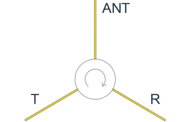
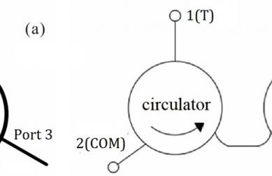
Signals circulate in one direction among ports (1→2→3→1) due to magnetized ferrite enforcing non-reciprocity. TX energy flows to the antenna; echoes are routed to the RX path.
Explanation (circulator): Biasing the ferrite breaks reciprocity so energy preferentially flows from one port to the next. System-wise this enables single-antenna TX/RX while maintaining port isolation, saving space and reducing interconnect losses.
- Pros: Simple pathing, low loss, inherent directionality.
- Watch-outs: Bias stability and mechanical assembly; isolation and RL can drift with temperature/stress.
2.2 Isolator (circulator + termination)
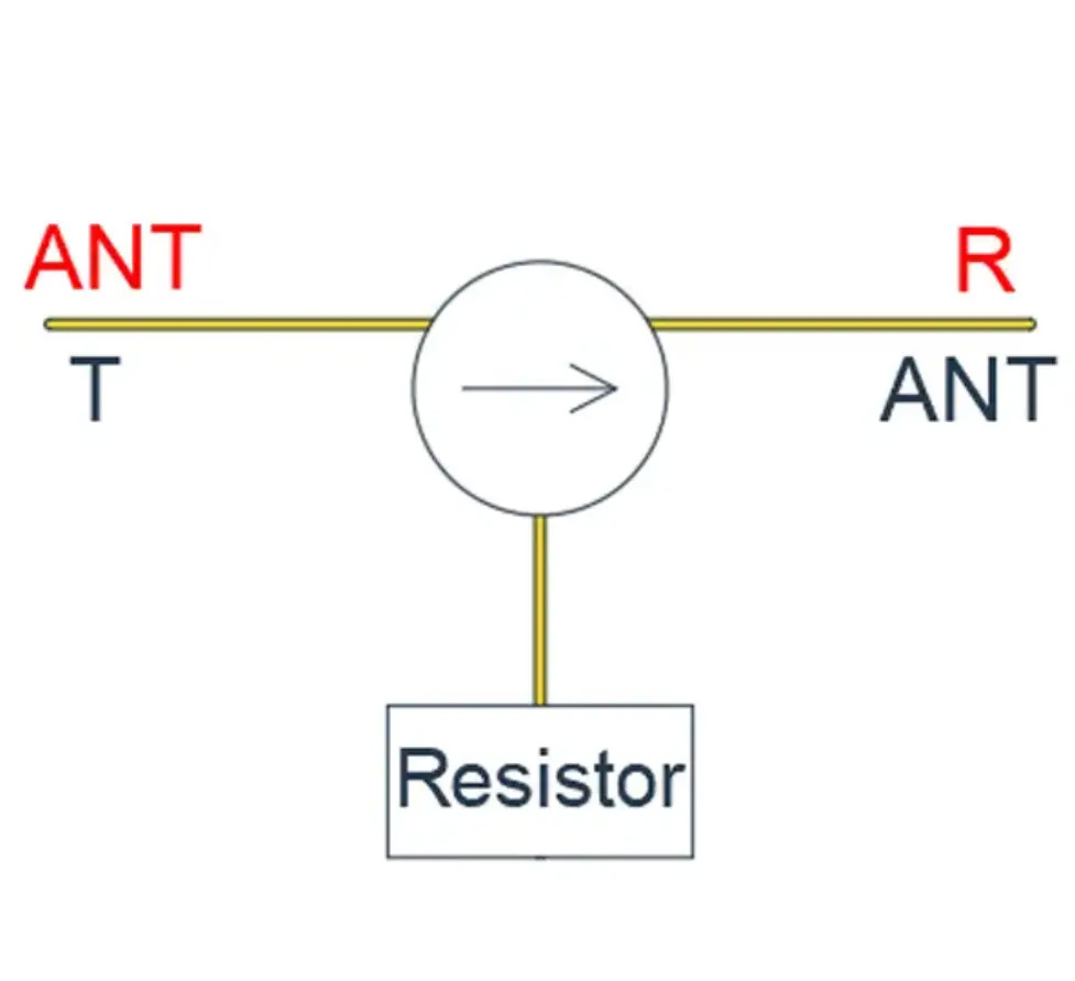
Terminate the third port with a matched load: forward signals pass, reverse signals are absorbed as heat in the load.
Explanation (isolator): The matched load converts reflected power to heat, preventing backflow into PAs/oscillators or into sensitive LNA inputs. In high-power/high-sensitivity systems this is a stability and reliability essential.
- Pros: One-way protection, higher VSWR tolerance, improved system stability.
- Watch-outs: Thermal design for the load; long-duration operation needs margin to avoid drift/demagnetization.
Reading the Specs: IL / Isolation / RL / Bandwidth / Power
Numbers matter only when measured consistently: same fixture, reference plane, calibration, and temperature. Below is a practical readout:
| Parameter | What it impacts | Engineering guideline |
|---|---|---|
| Insertion Loss (IL) | RX sensitivity, link budget, efficiency | Target <0.5–0.7 dB at band center; check flatness & temp drift |
| Isolation | Reverse suppression, decoupling, stability | ≥20–30 dB typical; leave 3–5 dB margin for high-power |
| Return Loss (RL)/VSWR | Matching, ripple, neighbor-stage impact | RL >14–20 dB preferred; unify reference plane (pads/connectors) |
| Bandwidth | Usable coverage, multi-standard coexistence | Wider bands simplify BOM; trade-offs with IL/Isolation |
| Power/Thermal | Reliability, drift, lifetime | Validate peak/avg vs duty cycle; ensure proper heat paths |
Layout tip:
Place the isolator close to the device it protects and keep RF lines short, straight, and symmetric.
Packaging & Integration: Waveguide/Coax vs Microstrip/Stripline
Different forms target different system goals. Waveguide/coax excels at high power and harsh environments; microstrip/stripline dominates where size, weight, and integration density matter.
| Form | Advantages | Cautions | Typical scenarios |
|---|---|---|---|
| Waveguide/Coax | High power, linearity, immunity | Bulky, heavy, higher assembly cost | High-power radar, harsh EM platforms |
| Microstrip/Stripline | Miniaturized, lightweight, PCB-conformal | More sensitive to thermal/mechanical/assembly consistency | Phased-array TR modules, 5G/SATCOM front-ends, portable devices |
Common pitfall: Chasing "peak" numbers but ignoring temp drift and lot-to-lot spread. Before mass production, run thermal cycling, vibration, and rework re-tests and document distributions.
Applications: Radar & Communication (system-level)
5.1 Radar: Shared antenna + LNA protection
Figure 5A. Circulator enables shared antenna; isolator shields the RX chain from strong echoes/mismatch.
Benefits (radar): Single-antenna operation with high detection range and robustness. With ~10 dB mismatch, isolators markedly cut RX overload probability.
- Implementation notes: Place the isolator near the LNA; ensure a solid thermal path for the load.
5.2 Communication: Stabilize PA, tame VSWR
Figure 5B. Isolator after PA stabilizes the load under antenna VSWR excursions; circulators can provide duplexing/decoupling when needed.
Benefits (communication): More stable EVM/ACLR and improved field reliability; returns decrease as load excursions are contained.
- Implementation notes: Budget thermal/spacing around the isolator; avoid strong coupling radiators nearby.
HZBEAT Microstrip Product Examples (three-figure matrix)
HZBEAT offers Typical Microstrip Isolators, Broadband Microstrip Isolators, and Miniaturized Microstrip Isolators, covering S–Ka bands.
- HMITB120T180G (Typical): Ku band, IL ≤0.7 dB, Isolation ≥16 dB — suited for SATCOM front-ends and Ku radar.
- HMITB60T180G-B2 (Broadband): 6–18 GHz, IL ≈1 dB — multi-standard communication and wideband radar.
- Miniaturized series: around 5–6 GHz, ~6.5×7.5 mm — ideal for high-density phased-array tiles.
Figure 6C, detailed note: Emphasis on space efficiency and mechanical robustness. Use repeatable torque/compression specs and run thermal/vibration stress tests to verify reliability in dense arrays.
| Category | Example P/N | Freq (GHz) | Typical IL (dB) | Typical Isolation (dB) | Notes |
|---|---|---|---|---|---|
| Typical | HMITB120T180G (CCW) | 12–18 | ≈0.6–0.7 | ≥16 | Ku radar/SATCOM; compact and integration-friendly |
| Broadband | HMITB60T180G-B2 (CCW) | 6–18 | ≈0.8–1.2 | ≈11–16 | Cross-standard devices; simplified BOM |
| Miniaturized | (Series example) | ~5–6 | ≈0.6 | ≈18 | Space-limited platforms; mind thermal/assembly stress |
Selection & Procurement Checklist
- Target function: duplexing (circulator) vs one-way protection (isolator).
- Band/Bandwidth: center frequency, 3 dB bandwidth, out-of-band suppression; single vs multi-band.
- Power/Thermal: peak/avg/duty cycle; thermal path and long-term drift.
- Matching/Measurement: unify fixture/reference/calibration; define acceptance windows (IL/Isolation/RL).
- Env/Reliability: temp/humidity/pressure, shock/vibration; PCN thresholds and re-qualification.
- Package/Assembly: waveguide/coax vs microstrip module; space/weight/rework strategy.
- Supply/Compliance: lot consistency, cadence; RoHS/REACH and any ITAR/EAR checks.
FAQ
❓Can a circulator fully replace an isolator?
No. An isolator (circulator+termination) provides one-way protection that a circulator alone cannot guarantee, especially for PA stability and LNA safety.
❓Are microstrip devices inferior to waveguide/coax?
Different strengths: microstrip is compact and integration-friendly; waveguide/coax shines at extreme power/EM immunity. Choose per platform power density and environment.
❓How to avoid “specs look fine but system drifts” after integration?
Lock down fixture/temp/reference in contracts; require pilot run + rework re-tests to align statistics.
Conclusion
Circulators and isolators are the invisible guardians of modern RF: the former routes, the latter protects. Together they keep systems stable under high power, high sensitivity, and complex EM conditions.
As 5G/6G, phased-array radar, and medical imaging advance, requirements skew toward broader bandwidth, miniaturization, and tighter consistency. Microstrip/stripline is becoming mainstream, and HZBEAT’s portfolio positions it to deliver reliable, high-performance solutions worldwide.
Bottom line: No robust RF system without robust circulators and isolators — and the right supplier turns good designs into great deployments.
References
- HZBEAT: Microstrip Isolator Catalog (Typical/Broadband/Miniaturized series)
- Pozar, D. M. Microwave Engineering, Wiley.
- Collin, R. E. Foundations for Microwave Engineering, McGraw-Hill.
- IEEE Trans. Microwave Theory and Techniques — Special Issues on non-reciprocal ferrite devices.
About the Author
HzBeat Editorial Content Team
Sara is a Brand Specialist at Hzbeat, focusing on RF & microwave industry communications. She transforms complex technologies into accessible insights, helping global readers understand the value of circulators, isolators, and other key components.
