SMT RF Isolators for Next-Gen Communication, Radar & Medical
Updated on:
Keywords: SMT RF isolator; surface-mount isolator; microstrip isolator;communication; radar; medical MRI; insertion loss; isolation; return loss; VSWR; bandwidth; power handling.
Introduction
An SMT (surface-mount) RF isolator is a compact, non-reciprocal microwave component that passes energy in one direction while providing high isolation in the reverse path. In modern front-ends—where channel counts scale and modules shrink—SMT isolators stabilize source impedance, suppress back-reflections, and protect LNAs/mixers from reverse power. Compared with coaxial or waveguide forms, SMT packages reduce interconnect loss, improve assembly repeatability, and enable high-density layouts—key for communication radios, phased-array radar tiles, and medical front-ends like MRI RF chains.
What is SMT & Why Choose SMT RF Isolators
What is Surface Mount Technology (SMT)?
Surface Mount Technology mounts components directly onto the surface of printed circuit boards (PCBs), enabling smaller footprints, higher assembly throughput, and stronger mechanical reliability than many through-hole approaches. For RF, SMT allows short interconnects and controlled geometries that reduce parasitics and variability.
Advantages of SMT for RF Isolators
-
Small & dense:Minimizes volume and height, ideal for array tiles and compact modules.
-
Lower interconnect loss:Short microstrip lines reduce cable/connector losses and variability.
-
Manufacturability:Reflow assembly scales to volume with repeatable performance.
-
System integration: Co-design pads, ground stitching, and shields with adjacent LNAs/mixers for optimum behavior.
Why SMT vs. Coaxial/Waveguide
Coaxial and waveguide parts can achieve excellent absolute performance, but they add size, connectors, torque requirements, and cable variability. SMT isolators excel when you need high channel density, compact layouts, and repeatability at scale.
Core Performance Metrics
Insertion Loss (IL)
Lower IL preserves receiver sensitivity and link margin. For compact modules across L/S/C/X/Ku/Ka-bands, a pragmatic target is < 0.5–0.7 dB at band center. Even a 0.1 dB improvement can ease gain budgeting and reduce noise-figure pressure across cascaded stages.
Isolation
Isolation suppresses back-reflections, inter-channel coupling, and stability risks. As a baseline, aim for ≥ 20–30 dB in dense modules; pursue higher if layout and shielding allow. Check isolation flatness across the full operating band and consider out-of-band behavior (pumps/spurs).
Return Loss / VSWR
Good matching (RL > 14–20 dB; VSWR ≈ 1.5–1.2) reduces ripple and improves stability of filters and mixers. Verify at temperature and process corners and after rework.
Bandwidth
Wider relative bandwidths typically increase IL; narrowband designs can trade bandwidth for lower IL and higher isolation at the frequency of interest.
Packaging & Integration Advantages
SMT isolators shrink size/weight, simplify assembly, and minimize interconnect variability. PCB co-design matters: pad geometry, copper thickness, ground stitching, short/symmetric return paths, and optional EMI shields. Manage CTE differences between laminates, ceramics, and magnets; define torque and coplanarity requirements to avoid stress. In arrays, per-channel isolators near LNAs often outperform a single shared device for stability and crosstalk control.
Application Playbooks: Communication, Radar, Medical
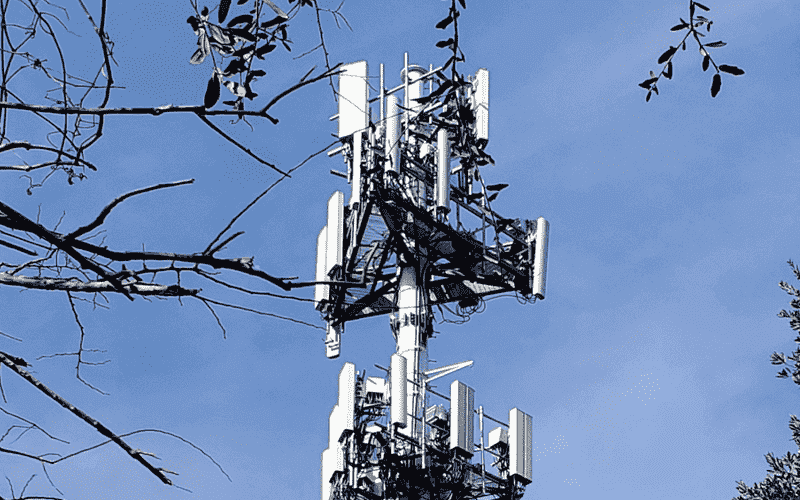
Communication
In 5G/6G radios and SATCOM front-ends, SMT RF isolators stabilize PA/LNA interfaces and improve matching in densely integrated RF modules. By suppressing reflections at critical junctions, isolators help maintain EVM/ACLR indirectly through better impedance control, while reducing the risk of unstable behavior when channels switch or antenna loads vary.
Radar
Phased-array tiles benefit from per-channel isolators located near T/R modules. This limits inter-element coupling that can distort beam patterns, improves calibration repeatability, and supports modular build-to-print strategies where many channels must behave consistently over temperature and time.

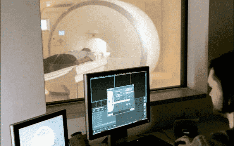
Medical
In MRI and other sensitive medical RF front-ends, isolators protect receive chains from reverse power and stabilize impedance around preamps and switches. The small SMT form factor helps fit within tight mechanical envelopes without adding connector losses or cable variability.
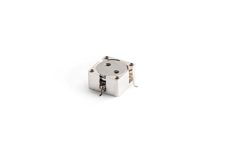
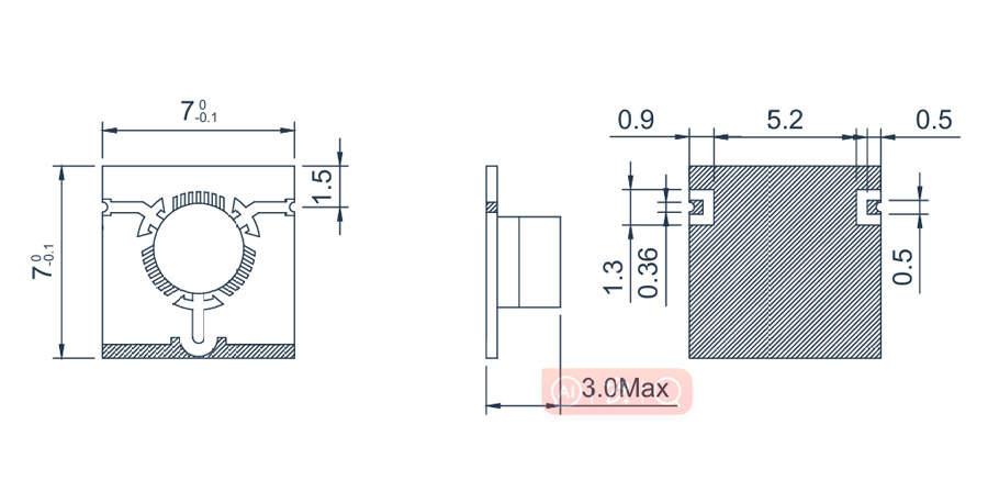
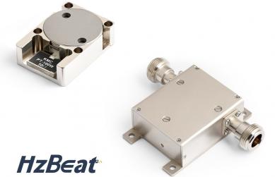
HzBeat SMT Isolator Highlights (Gallery & Specs)
HzBeat’s SMT/microstrip isolators emphasize compact footprints, consistent matching, and manufacturability for dense modules. Typical design goals include low insertion loss, flat isolation across the working band, and robust solder-joint reliability. If you need band-specific footprints or custom shields, our applications team can co-design the land pattern, ground stitching, and verification plan with you.
| Band (GHz) | Insertion Loss | Isolation | Return Loss | Package | Representative Uses |
|---|---|---|---|---|---|
| 8–12 (X) | ≤ 0.6 dB | ≥ 20 dB | ≥ 15 dB | SMT microstrip | Compact radar modules |
| 14–18 (Ku) | ≤ 0.7 dB | ≥ 22 dB | ≥ 16 dB | SMT microstrip | SATCOM user terminals |
HzBeat support customization!
How to Select the Right SMT RF Isolator
- Define band & bandwidth: center frequency, 3-dB bandwidth, and out-of-band risks (pumps/spurs).
- Set performance targets: IL, isolation, RL/VSWR, package size/height, shield options, and thermal constraints.
- Co-design & simulate: pads, ground stitching, RF line geometry; run EM/circuit co-sims to check parasitics and matching.
- Qualification plan: environment range, cycles, acceptance criteria; document fixtures and calibration trees.
- Vendor documentation: at-band S-parameters, assembly/handling/storage notes, lifecycle policy and change control.
- Pilot build & review: verify repeatability across boards/lots and after rework; log drift and decide go-to-production gates.
FAQ
1)Do isolators add too much loss for sensitive receive chains?
Well-designed SMT isolators can keep IL below ~0.5–0.7 dB at band center—preserving sensitivity while improving stability and repeatability.
2)Can one isolator cover multiple channels?
Shared parts are possible, but per-channel isolators placed near LNAs usually give better stability and crosstalk control in arrays.
3)Can HzBeat customize footprints and shields?
Yes—custom pads, z-height, and shield options are available to fit dense layouts and mechanical constraints.
References
Everything RF — “RF/Microwave Isolators: Overview & Selection Considerations.” IEEE Microwave Theory & Technology (2022–2025) — Non-reciprocal components: design & measurement.
Keysight / Rohde & Schwarz application notes — S-parameter measurement best practices. HzBeat product pages & datasheets — SMT/microstrip isolators (photos and mechanical drawings).
Relateds


About the Author

HzBeat Editorial Content Team
Sara is a Brand Specialist at Hzbeat, focusing on RF & microwave industry communications. She transforms complex technologies into accessible insights, helping global readers understand the value of circulators, isolators, and other key components.