Hybrid RF Front-End: Combining Directional Couplers, Isolators, and Filters for Precision
Updated on:
Keywords: Hybrid RF Front-End, Directional Coupler, RF Isolator, RF Filters, Nonreciprocal Microwave Components, Signal Integrity, Scattering Parameters, VSWR, Return Loss
An IEEE-style technical brief for engineers and decision-makers
Abstract — This article examines a hybrid RF front-end architecture that integrates directional couplers, nonreciprocal isolators, and frequency-selective filters. We outline the roles of each component in managing forward/reflected waves, protecting active devices against load-induced instabilities, and enforcing spectral masks. Design trade-offs are quantified in terms of coupling/directivity, insertion loss and return loss, isolation, group delay, and linear/nonlinear power handling. Practical integration guidance and application contexts (radar, satellite links, 5G/6G mmWave) are included, with references to authoritative sources and instrumentation practices.
1. Introduction
RF front-ends must simultaneously ensure signal integrity, spectral compliance, and stability. A hybrid approach—combining directional couplers for power sampling and reflectometry, isolators for nonreciprocal protection, and filters for in/out-of-band shaping—offers a robust path to consistent performance across changing source/load conditions and harsh environments.
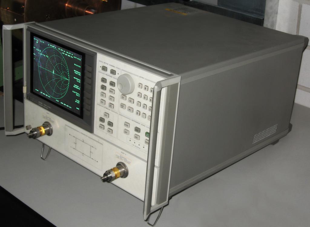
Fig. 1 — VNA readout (S11, S21). Credit: AllenMcC., CC BY-SA 3.0.
2. Technical Overview and Roles
2.1 Directional Coupler
A directional coupler samples forward and reverse traveling waves using coupled transmission structures (microstrip, stripline, coax, waveguide). Its ideal behavior provides strong directivity (minimal reverse leakage) and a well-defined coupling factor for calibration and power monitoring.
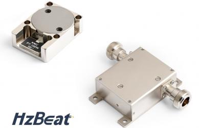
2.2 Nonreciprocal Isolator
Ferrite-based isolators exploit magnetically biased anisotropy (e.g., Faraday rotation or junction resonance) to realize a two-port with low loss in the forward direction and high attenuation in reverse, protecting PA stages from mismatch and preventing oscillations.
2.3 RF/Microwave Filters
Filters enforce spectral masks and desensitize receivers by suppressing out-of-band energy. Practical topologies—Butterworth, Chebyshev, Elliptic, cavity, LTCC thin-film—trade passband ripple, roll-off, Q, and group delay.
Fig. 2 — Microstrip directional coupler. Credit: Binarysequence, CC BY-SA 4.0.
3. Key Parameters and Co-Design Trade-offs
3.1 Couplers: Coupling, Directivity, and Insertion Loss
Selecting a −10 dB vs −20 dB coupler influences monitoring accuracy and additional loss budget. Directivity (in dB) governs separation of forward/back waves; inadequate directivity corrupts reflected-power estimates at high VSWR.
3.2 Isolators: Isolation, Return Loss, and Power Handling
The isolator’s forward path should exhibit low insertion loss and good return loss to avoid degrading noise figure and gain flatness. Reverse isolation (>20–30 dB) limits re-entrant energy to the PA.
3.3 Filters: Selectivity vs. Distortion
Elliptic responses offer steep skirts at the expense of passband ripple and group-delay variation, while Butterworth responses are maximally flat but gentler. In transmitter chains, filter linearity and power handling are critical.
3.4 End-to-End View: NF, PAE, ACPR, and EVM
Co-design balances insertion loss (coupler, isolator, filter) against required selectivity and stability. Excess loss increases PA output demand and degrades receiver noise figure; insufficient selectivity erodes ACLR/ACPR and EVM.
4. Integration Challenges and Practical Guidance
Layout & Matching.
Keep coupler coupled lines tightly tolerance-controlled; ensure isolator interfaces are well-matched (target low VSWR). Place filters where they see a controlled impedance environment; avoid hot spots near high-Q resonators.
- Packaging & Media: Microstrip/stripline ease integration; cavity and LTCC offer higher Q and power handling at the cost of size/complexity.
- Thermal & Bias: Ferrite isolators require stable magnetic bias; temperature affects permeability and isolation.
- Calibration & Test: Use a VNA to extract S-parameters across operating temperatures; verify directivity-limited uncertainty for coupler-based power sampling.
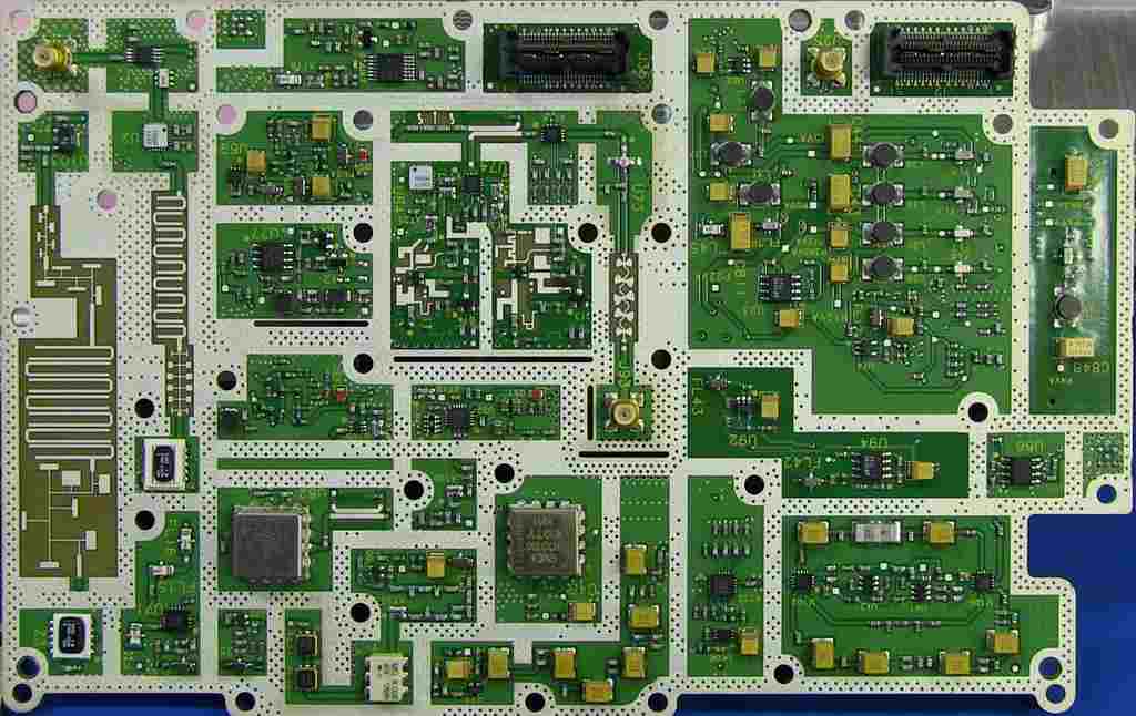
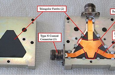
Fig. 3 — Stripline filters on PCB. Credit: Binarysequence (EEVblog), CC BY-SA 3.0.
Component Selection (with HzBeat internal links)
When system stability and reverse-power immunity are primary risks, prioritize a low-loss isolator early in the chain (e.g., after PA or sensitive source). For sampling and protection around antennas, choose couplers with sufficient directivity and coupling for monitoring without undue loss. Filters should be placed to meet emissions and blocking requirements while minimizing group-delay distortion near the signal band.
Related reading on component families: Microstrip Circulators · Drop-in Circulators · Coaxial Circulators · Waveguide Circulators
5. Application Examples
- Radar T/R Modules (L–Ka): Couplers enable in-situ calibration and VSWR alarms; isolators suppress leakage/backswing into PAs; pre-selector cavity filters mitigate out-of-band jamming.
- Satellite Payloads: Nonreciprocal elements and high-Q filters maintain linearity and stability under thermal drift; cross-coupled resonators achieve stringent masks.
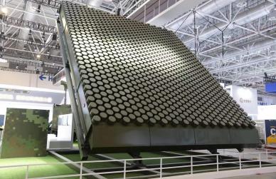
- 5G/6G mmWave: Compact thin-film/LTCC filters and miniature couplers provide monitoring and spectral hygiene in phased arrays; isolators protect mixed-signal PAs in beam-forming chains.
6. Future Outlook
Trends point to hybrid integration across ferrite junctions, thin-film filters, and high-Q cavity modules, with tunability (center frequency, bandwidth, transfer function) to support multi-band operation and adaptive linearization. Continued material advances and packaging co-design will further reduce loss and footprint while preserving isolation and selectivity.
References
- Keysight, “Power Flow and Directional Couplers,” App Note 5992-0333.
- All About Circuits, “Introduction to the Directional Coupler for RF Applications,” Jan. 19, 2024.
- Wikipedia, “Isolator (microwave)” (nonreciprocity, S-matrix overview).
- RF-CI, “Operating Principles of Ferrite Circulators and Isolators,” Knowledge Base KB-001 (PDF).
- Levy, Snyder, Matthaei, “Design of Microwave Filters,” IEEE Trans. MTT, vol. 50, no. 3, 2002.
- HzBeat Microstrip Circulator page: category coverage notes for K‑band capable products.
- Thomas, “Cross-Coupling in Coaxial Cavity Filters—A Tutorial Overview,” IEEE Trans. MTT, vol. 51, no. 4, 2003.
- Mini-Circuits Blog, “A Quick Guide to RF & Microwave Filter Topologies,” Jan. 5, 2022.
- Microwave Journal, “Advances in Microwave Filter Design Techniques,” Nov. 17, 2008.
- IEEE MTT-S Resource Center, “Introductory Course on Microwave Filters.”
Image credits
- Fig. 1 — “NetworkAnalyzer.jpg,” AllenMcC., Wikimedia Commons, CC BY-SA 3.0.
- Fig. 2 — “Microstrip Directional Coupler.jpg,” Binarysequence, Wikimedia Commons, CC BY-SA 4.0.
- Fig. 3 — “Spectrum Analyser PCB.jpg,” Binarysequence (EEVblog), Wikimedia Commons, CC BY-SA 3.0.
Relateds

About the Author

HzBeat Editorial Content Team
Marketing Director, Chengdu Hertz Electronic Technology Co., Ltd. (Hzbeat)
Keith has over 18 years in the RF components industry, focusing on the intersection of technology, healthcare applications, and global market trends.