In-Depth Analysis of the Three Core Metrics of RF Components
Updated on:
Keywords: Core Metrics of RF Components,VSWR,Insertion Loss,Isolation
Table of Contents
- Introduction
- VSWR - The Art of Impedance Matching in an RF Link
- VSWR - The Art of Impedance Matching in an RF Link
- Insertion Loss - The "Funnel Effect" of RF Energy
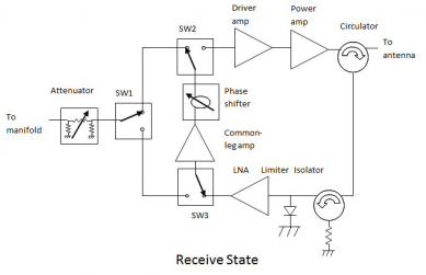
- Isolation - Building "Sound-Proof Walls" inside Multi-Port Devices
- Coordinated Optimisation - The "Impossible Triangle" of RF Design
- Future Trends - From Semiconductor Materials to AI-Assisted Design
Introduction
In today's world-where millimetre-wave (mmWave) communications and space-ground integrated networks are surging ahead-the optimisation of RF components has become the key to breaking the capacity bottleneck of modern systems. Voltage Standing Wave Ratio (VSWR), insertion loss and isolation are not merely performance figures; they guide every stage of RF-link design. Starting from electromagnetic theory and moving through cutting-edge applications such as 5G base stations and satellite payloads, this article uncovers the physics behind these metrics and the logic engineers use to optimise them.
VSWR - The Art of Impedance Matching in an RF Link
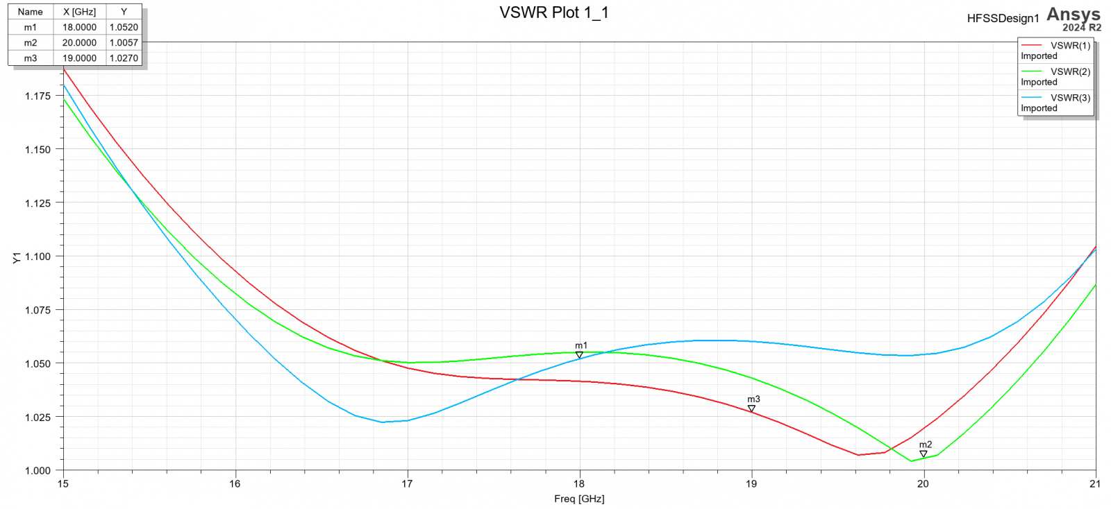
VSWR represents the "game" between incident and reflected waves in an RF system. Perfect impedance matching among source, transmission line and load yields a VSWR of 1-the ideal. In practice, material dispersion and manufacturing tolerances introduce mismatch. Once VSWR exceeds 1.5, 5.7 % of the incident power is reflected, potentially overheating or destroying high-power amplifiers.
The challenge intensifies in 5G mmWave base stations. At 28 GHz (λ ≈ 10.7 mm), the tiniest dimensional error in connectors or PCB traces causes significant impedance variation. Field data from a 5G AAU show that raising VSWR from 1.2 to 1.8 drops EIRP by roughly 2.3 dB-shrinking cell radius by 15 %. Engineers counter this with multi-section impedance-taper structures (e.g., Chebyshev transformers) that hold VSWR below 1.2 over wide bandwidths.
Insertion Loss - The "Funnel Effect" of RF Energy
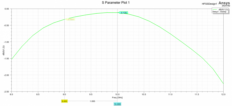
Insertion loss quantifies signal attenuation through a component and stems from three mechanisms: Ohmic (conductor) loss, dielectric polarisation loss and radiation loss at discontinuities. In microwave-ceramic filters, a tan δ increase of 0.001 can add ~0.1 dB of loss-one reason 5G base stations favour low-loss Al₂O₃ substrates.
Spaceborne links push requirements to the extreme. After 36 000 km of free-space travel, GEO satellite signals are faint; each RF stage must keep insertion loss under 0.3 dB. A Ka-band satellite transponder using LTCC's 3-D wiring reduced via count and achieved 0.15 dB insertion loss at 30 GHz-50 % better than conventional PCBs. Note the temperature dependence: raising ambient temperature from 25 °C to 85 °C boosts coax-cable insertion loss by ~12 %, underscoring the necessity of thermal management.
Isolation - Building "Sound-Proof Walls" inside Multi-Port Devices
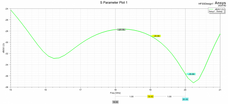
Isolation measures how well an RF device prevents signal leakage between ports. In duplexers and circulators, high isolation avoids transmit/receive crosstalk. A 5G FDD phone duplexer, for instance, demands ≥ 55 dB isolation; otherwise, the transmit signal swamps the LNA, degrading sensitivity.
Large-scale MIMO arrays drive continual innovation: a 64T64R 5G base station needs > 30 dB isolation between adjacent elements to tame mutual coupling. Mainstream techniques include:
- Electromagnetic band-gap (EBG) ground planes-periodic patches create a stop band blocking surface waves.
- Polarisation diversity-orthogonally polarised antenna pairs exploit field orthogonality for ≥ 30 dB isolation.
- Metamaterial absorbers-resistive structures inserted between elements convert RF energy to heat, adding 10–15 dB.
Coordinated Optimisation - The "Impossible Triangle" of RF Design
VSWR, insertion loss and isolation often pull in different directions, forming a trade-off reminiscent of the Shannon limit. Radar systems illustrate this vividly:
- Precision-tracking radar (e.g., missile guidance) prizes ultra-low VSWR (< 1.15) for maximum power efficiency and waveform fidelity.
- Over-the-horizon (OTH) early-warning radar lives or dies by minimal insertion loss (< 0.2 dB) and extreme isolation (> 70 dB) to protect its ultra-sensitive receiver.
- Phased-array radar T/R modules must juggle low VSWR, low insertion loss and high isolation in a space-constrained package-the quintessential “impossible triangle”.
A real-world front-end illustrates the tension: reducing VSWR from 1.8 to 1.3 via a more complex matching network raised insertion loss by 0.2 dB; chasing 60 dB isolation in the duplexer demanded another 0.15 dB sacrifice.
Application-Specific Priorities
| Application | Insertion-Loss Target | Isolation Target | VSWR Target | Priority Logic |
|---|---|---|---|---|
| Mobile base station | < 0.5 dB | > 30 dB | < 1.50 | VSWR > Insertion loss > Isolation |
| Radio-astronomy receiver | < 0.1 dB | > 70 dB | 1.10-1.25 | Insertion loss > Isolation > VSWR |
| GEO satellite payload | < 0.3 dB | > 50 dB | < 1.20 | Insertion loss ≈ Isolation > VSWR |
| Precision-tracking radar | < 0.3 dB | > 60 dB | < 1.15 | VSWR ≈ Insertion loss > Isolation |
Future Trends - From Semiconductor Materials to AI-Assisted Design
The rise of third-generation semiconductors (GaN, SiC) materially improves metrics under high-temperature, high-power conditions. A GaN PA measured at 100 °C shows 0.3 dB less insertion loss than a GaAs counterpart while holding VSWR ≤ 1.2.
On the methodology front, machine-learning-driven optimisation is reshaping RF design. Deep-neural-network models can perform multi-metric optimisation in hours instead of weeks; one case raised a circulator's VSWR, insertion loss and isolation by over 15 % simultaneously.
From massive 5G roll-outs to early 6G research, the evolution of RF components moves in lock-step with system demands. Grasping the physics of VSWR, insertion loss and isolation-and mastering their scenario-specific optimisation-is vital to smashing the limits of RF links. As new materials, processes and AI-driven design tools emerge, the ceiling on these three metrics will keep rising, laying a solid foundation for tomorrow's communication technologies.
Relateds

About the Author

HzBeat Editorial Content Team
Sara is a Brand Specialist at Hzbeat, focusing on RF & microwave industry communications. She transforms complex technologies into accessible insights, helping global readers understand the value of circulators, isolators, and other key components.