Custom RF Circulator Design and Manufacturing Guide 2026: Price, Performance, and Applications
Updated on:
Keywords: custom RF circulator, RF circulator design, RF circulator manufacturer, circulator price, microwave circulator, isolator, radar, satcom, 5G, mmWave
1) Introduction
Custom RF circulators are passive, non‑reciprocal three‑port microwave components designed to route energy in a single direction (1→2→3) while suppressing reverse propagation. Compared with off‑the‑shelf catalog parts, custom units allow tighter control over band and bandwidth, insertion‑loss (IL) targets, isolation (Iso) levels, and power/thermal performance under mission‑specific environments. This degree of tailoring is increasingly relevant as systems scale to mmWave bands, pursue wider instantaneous bandwidths, and must survive harsher thermal and mechanical profiles in aerospace, automotive radar, and remote terminals.
In 2025 the industry context is defined by three forces: (i) rising operation bands (X/Ku/Ka and pilot W‑band deployments) in defense radar and SatCom payloads; (ii) wider instantaneous bandwidths demanded by software‑defined radios and agile front ends; and (iii) greater environmental robustness for platforms exposed to temperature extremes, shock/vibration, and radiation. In this landscape, a circulator is not simply a wave‑routing accessory; it is a performance‑critical protection and duplexing element that influences link budgets, mean time between failures, and total cost of ownership.
For product categories and examples, see: Microstrip Circulators · Drop‑in Circulators · Waveguide Circulators · Isolators.
2) Principles and Device Types
Operating principle. Ferrite‑based junction circulators exploit gyromagnetic (ferrimagnetic) resonance under a static bias field. The ferrite’s permeability becomes anisotropic, supporting non‑reciprocal phase shifts that enforce a preferred rotation of the RF fields. A classic Y‑junction couples the three ports such that power incident at Port 1 is delivered to Port 2 while Port 3 is isolated; reversing the direction similarly routes 2→3 and 3→1. Proper bias and matching realize the desired bandwidth with low loss.
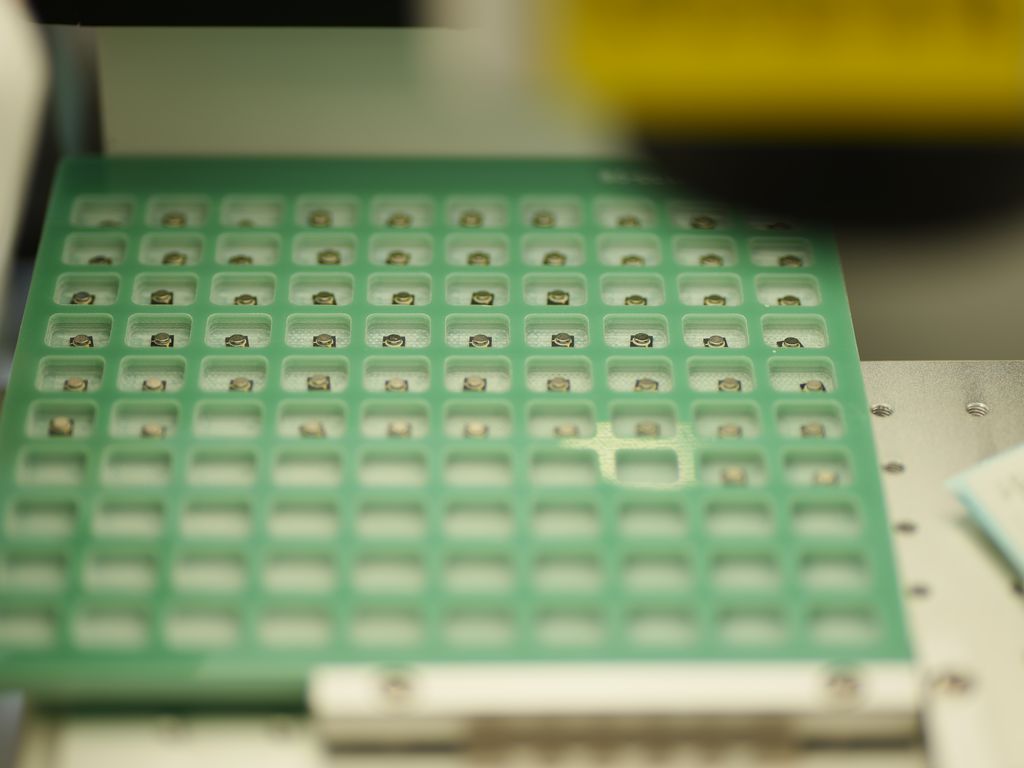
Microstrip/SMD. Compact, lightweight, and PCB‑integrable; suitable for L‑ to Ku‑band with moderate power. They minimize assembly steps and are attractive for array panels and volume production. Thermal path design (vias, baseplate, copper spreaders) is essential for CW operation. See category overview at hzbeat.com/microstrip-circulator.
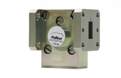
Drop‑in. Machined housings and grounding through screws offer improved repeatability and thermal conduction vs. pure PCB variants. Drop‑ins serve as a bridge between microstrip and coax/waveguide in power capability and are common in pulsed radar T/R modules. Explore drop‑in circulators.
Coaxial. Connectorized packages simplify lab integration and instrumentation. They trade size and cost for convenience and test flexibility.
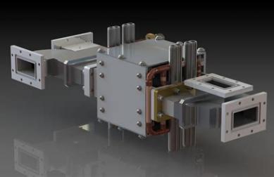
Waveguide. For high power and low IL at microwave/mmWave frequencies, waveguide circulators provide excellent field confinement and thermal margins. They are prevalent in satellite payload chains and high‑power radars. See waveguide circulators.
From circulator to isolator. Terminating one port with a matched load realizes an isolator, protecting upstream LNAs or PAs from reflected energy. In high‑peak environments (radar, EMC tests), the load’s power‑handling and heatsinking become the limiting factors. See Isolator notes.
3) Key Specifications and Trade‑offs
Custom designs begin with a specification that reconciles frequency plan, allowed IL, required Iso, return loss (or VSWR), power level (CW and peak), and package constraints. Rigorous allocation of margins is critical: a few tenths of a dB in IL can materially shift system‑level efficiency and thermal headroom, while a few dB in isolation may determine EMI susceptibility and PA survivability under severe mismatch.
Electrical
- Center frequency f0 and bandwidth
- Insertion loss (IL) across the band
- Isolation (Iso) between non‑preferred ports
- Return loss / VSWR and matching topology
Power & Environment
- Peak/CW power handling and duty cycle
- Thermal path: baseplate, vias, spreaders
- Operating temperature, shock/vibration
Package & Integration
- Microstrip, drop‑in, coax, waveguide
- Footprint/height limits; connectors/flanges
- EMC/EMI containment; magnetic bias scheme
| Objective | Trade‑off | Notes |
|---|---|---|
| Lower IL | Narrower BW, larger ferrite, tighter bias | Optimize matching networks; control process tolerances |
| Wider BW | IL penalty; multi‑section transitions | Consider stepped impedance matching |
| Higher Power | Thermals dominate | Model copper loss and field uniformity |
Integration examples: Microstrip, Drop‑in, Waveguide, and paired Isolators.
4) Custom Design Workflow
- Requirements capture. Define bands/BW, IL/Iso/VSWR targets, power (CW/PK), package, footprint, interfaces, environment (temperature, shock/vibe), and compliance (RoHS/REACH, MIL‑STD/space as applicable). A concise RFQ checklist reduces back‑and‑forth.
- EM design and materials. Select ferrite type and geometry, determine biasing scheme (permanent magnet, external coil), and junction layout (Y‑junction, post dimensions). The permeability tensor under bias is tuned to center the operating band.
- Simulation. Full‑wave EM simulation (e.g., HFSS, CST, COMSOL) refines S‑parameters, field distributions, and thermal behavior. Sensitivity studies quantify tolerance to ferrite dimensions, air gaps, and fasteners.
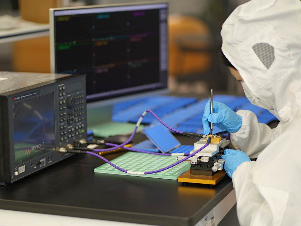
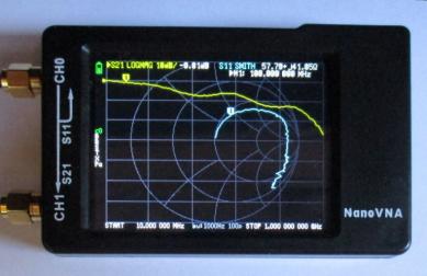
- Prototype and test. Build first articles, then measure S‑parameters on a calibrated VNA (SOLT/T/R/L) across temperature. Validate peak and CW power limits; observe spectral purity and spurious responses.
- Iterate and converge. Adjust matching networks, bias strength, and assembly stack‑ups to converge IL/Iso/VSWR to targets with margins.
- Qualification and ramp. Establish outgoing inspection, golden units, fixtures, and environment profiles for production. Document statistics and Cpk for IL/Iso consistency.
5) Manufacturing and Qualification
- Ferrite processing. Powder selection, pressing, sintering, and precision grinding control the magnetic and dimensional properties that set IL/Iso and temperature drift. Post‑processing includes lapping/flatness control to secure intimate contact with conductors and minimize parasitic gaps.
- Magnetics and biasing. Permanent magnets provide compact bias; some designs employ coils for tunability. Field uniformity across the junction is essential to sustain isolation across the operating band; shims and keepers may be used to shape flux and reduce stray fields into adjacent circuits.
- Assembly. Stack‑ups combine ferrite disks, matching posts, conductors, spacers, and housings. Tolerances on post height and air gaps are central to repeatability. For high power, baseplates and flange interfaces are machined for thermal conduction and flatness.
- Testing. End‑of‑line (EOL) testing verifies S‑parameters, power handling, temperature cycling, and mechanical robustness (shock/vibration). For demanding programs, additional screening—burn‑in, outgassing (space), and radiation sensitivity—may be required.
- Compliance. ISO 9001 for QMS; RoHS/REACH for materials; MIL‑STD‑810 for environmental; ECSS/NASA standards for space. Traceability and data retention are critical for aerospace and defense audits.
6) Price Drivers and 2025 Trends
Pricing for custom circulators is not a list‑price exercise; it reflects physics, qualification scope, and supply‑chain realities. The following drivers generally dominate in 2025:
- Frequency and bandwidth. Higher bands (Ku/Ka/mmWave) and wider instantaneous bandwidths demand tighter ferrite properties, refined junction geometries, and lower IL across a larger span—raising design effort and yield risk.
- IL/Iso targets. Sub‑0.4 dB IL or ≥ 25–30 dB isolation across wide bands is achievable but typically increases size, magnet strength, matching complexity, and screening time.
- Power handling and thermals. High CW power paths require low thermal resistance to the baseplate and careful conductor loss management. Peak power (pulsed radar) adds breakdown and bias stability concerns.
- Package choice. Waveguide units tend to cost more than coaxial, which tend to cost more than drop‑in and microstrip; however, the correct choice is dictated by power, loss, and environmental constraints.
- Qualification and documentation. Aerospace and defense programs entail extended screening and documentation, adding engineering NRE and unit cost.
- Volume and learning curves. Larger orders amortize NRE and improve yields via process learning and tighter SPC.
For inquiries and structured quotes see: RFQ Center.
Market backdrop. Industry analyses of RF/microwave passive components indicate steady growth through the decade driven by radar modernization, new satellite constellations, and mmWave infrastructure. Reports (e.g., MarketsandMarkets; independent research portals) project compound annual growth rates in the mid‑single to low‑double digits depending on segment and region. While methodologies differ, most agree that higher‑frequency and higher‑power segments outpace legacy L‑/S‑band categories, reflecting ongoing platform upgrades and spectrum expansion.
7) Applications and System‑Level Guidance
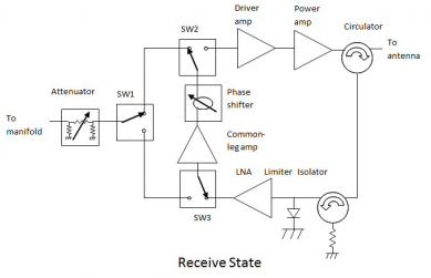
Radar Transmit/Receive (T/R) Modules
Custom circulators protect solid‑state PAs from high VSWR during antenna scan extremes or icing events while providing duplexing between the transmitter and receiver paths. Pulsed operation places stress on peak power handling and hot‑bias stability. Thermal design focuses on baseplate conduction and heat spreading into module frames. For phased arrays, repeatability across hundreds or thousands of elements becomes a yield and calibration challenge.
Satellite Communications (Gateways, Payloads, Terminals)
Waveguide circulators at Ku/Ka bands offer low loss and high power margins; drop‑in and microstrip variants support compact terminals. Radiation tolerance, thermal cycling, and vacuum outgassing drive material choices and screening levels. Tight IL targets preserve EIRP and G/T budgets in long‑haul links.
5G/mmWave Infrastructure and Test
In test sets and over‑the‑air (OTA) chambers, connectorized circulators serve as configurable protection for high‑power amplifiers and as routing elements in duplex testbeds. In infrastructure radios, microstrip/drop‑in designs offer board‑level integration, while thermal density and cost steer the package selection.
Automotive Radar
High‑volume reliability and temperature range dominate; compact microstrip/SMD circulators are favored. Low IL is leveraged to extend detection range or to reduce PA load. Automotive EMC constraints motivate careful magnetic shielding and PCB keep‑out zones.
Medical and Scientific
In MRI and industrial heating, high CW power handling and ultra‑low IL are prioritised. Package selection tilts toward coaxial or waveguide with generous thermal margins and serviceable loads for isolator implementations.
8) Indicative Price vs Frequency
The following graphic is an illustrative summary—not a quotation. It reflects typical cost escalation with frequency as designs enter Ku/Ka/mmWave and target tighter IL/Iso performance. Exact pricing depends on the full specification, qualification scope, and volume.
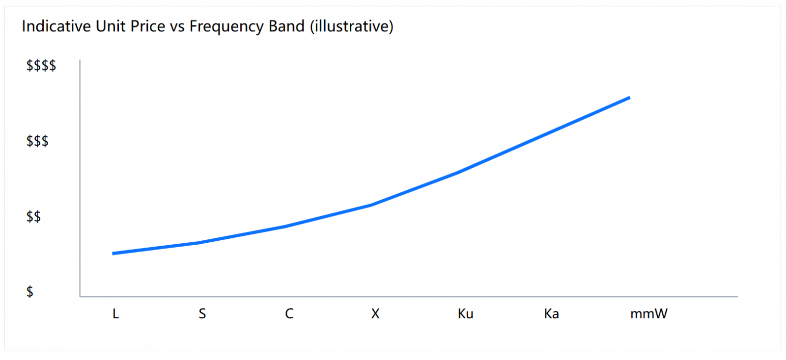
Indicative trend only. Request a tailored RFQ for precise pricing and lead time.
9) Selecting a Design/Manufacturing Partner
| Criterion | What to look for | Why it matters |
|---|---|---|
| EM design expertise | Ferrite physics, junction modeling, bias control | Achieve IL/Iso targets with margin |
| Process capability | Ferrite grinding, tight tolerances, SPC | Repeatability across lots |
| Power/thermal know‑how | Baseplate design, copper loss modeling | High CW/PK robustness |
| Test & qualification | VNA, power rigs, temp cycling, MIL/space | Field reliability, certification |
| Supply chain | Materials resilience, lead‑time discipline | Predictable schedules |
| Commercial model | Transparent NRE and volume tiers | Budget and lifecycle planning |
10) FAQ
Q1. What information is needed for a custom circulator quote?
Band(s) and bandwidth, IL/Iso/VSWR targets, power levels (CW/PK), package preference and footprint envelope, interface standard, operating temperature range, environmental/qualification requirements (e.g., MIL‑STD‑810, space screening), documentation needs, and expected volume/roadmap.
Q2. Can one design cover multiple split bands?
Sometimes. If the required bands are close, a single design with appropriate matching networks can cover both; widely separated bands typically need separate variants or a reconfigurable bias/matching approach.
Q3. How to validate power handling safely?
Use stepped power testing with thermal monitoring, verify bias stability, characterize IL/Iso drift under temperature, and inspect for arcing/flashover in high‑field regions. For isolators, validate the load’s temperature rise and failure modes.
Q4. When is waveguide preferred over microstrip/drop‑in?
When power density is high, IL budgets are tight, or the band is in Ku/Ka/mmWave where conductor and dielectric losses accumulate; waveguide’s superior confinement and thermal interfaces often justify size and cost.
Q5. How does temperature affect performance?
Ferrite properties and magnet bias shift with temperature, moving the effective center frequency and altering IL/Iso. Designs for harsh environments apply temperature compensation, robust bias margins, and acceptance testing across the profile.
Relateds
About the Author

HzBeat Editorial Content Team
Sara is a Brand Specialist at Hzbeat, focusing on RF & microwave industry communications. She transforms complex technologies into accessible insights, helping global readers understand the value of circulators, isolators, and other key components.