What Are RF Isolators, And What Are They Used For?
Updated on:
Keywords: RF isolator, RF isolators, microwave isolator, ferrite isolator, broadband RF isolator, RF circulator, RF isolator manufacturer, RF isolator supplier, waveguide isolator, microstrip isolator
RF isolators look like small passive components, but they quietly protect some of the most expensive hardware in a microwave system. In radar, satellite links, 5G radios and RF test benches, a single high-quality RF isolator can decide whether your chain runs clean and stable — or burns up under reflected power.
1. What Is an RF Isolator?
An RF isolator is a two-port, non-reciprocal microwave component that lets RF energy travel in one direction while strongly attenuating power in the opposite direction. In other words, an RF isolator passes forward power with low insertion loss and absorbs or redirects reverse power so that it cannot damage upstream devices.
Most RF isolators are ferrite isolators. They use magnetized ferrite materials in a guided structure (microstrip, stripline, coaxial line or waveguide). Under bias, these ferrites create non-reciprocal propagation, which is what gives the RF isolator its “one-way” behavior.
In a typical block diagram, an RF isolator is placed directly after a power amplifier, frequency converter or oscillator. The isolator provides a more ideal 50 Ω environment, improves system linearity, and protects sensitive stages from reflected power coming back from antennas, filters, cables, duplexers or mismatched loads.
Key idea:
an RF isolator is like a check valve in a plumbing system. RF power can flow forward, but any power trying to come back is blocked and sent to a termination instead of into your amplifier.
2. Why RF Isolators Are Essential in RF & Microwave Systems
In real-world RF systems there is always some mismatch and reflected power. Without a properly specified microwave isolator, this reflected energy can create serious problems:
- Damage to RF power amplifiers (PAs): high VSWR and reverse power can overheat devices and cause catastrophic failure.
- Gain compression and intermodulation: reflections disturb bias and loading, increasing distortion and IMD.
- Spurious oscillations: feedback loops formed by reflections may cause unstable oscillations.
- Degraded noise figure: reflected signals can leak into sensitive receiver stages.
A correctly chosen RF isolator acts as a quiet bodyguard. It absorbs the reverse power and keeps the microwave chain working in its designed operating region, even when the antenna or load is temporarily mismatched.
3. Common Types of RF Isolators
Modern RF isolators cover frequencies from tens of megahertz to well beyond 40 GHz, using different mechanical formats depending on the application. Below are the most common RF isolator types you will encounter when sourcing parts.
3.1 Microstrip RF Isolators (SMT / Chip-Level)
Microstrip isolators use a planar microstrip line on a ferrite substrate with a permanent magnet. These RF isolators are extremely compact and are often supplied in surface-mount (SMT) or chip-level packages. They are ideal for small RF modules, 5G radios, UAV data links and other high-density designs where PCB area is limited.
Typical use cases for microstrip RF isolators include low-power to medium-power stages from L-band up to Ka-band, especially where miniaturization and broadband performance are key.
Learn more on HzBeat: Broadband Microstrip Isolator
3.2 Drop-in RF Isolators
Drop-in isolators (also called “flangeless” or PCB-mount isolators) are designed to be dropped into a machined pocket in a metal carrier or housing. They provide excellent thermal performance, good isolation and very low insertion loss across a defined band.
These RF isolators are widely used in radar TR modules, SATCOM ODU units, and multi-channel transmitters where engineers need robust performance and repeatability in volume production.
Related HzBeat RF components: Drop-in Circulator Series
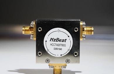
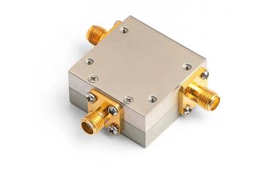
3.3 Coaxial RF Isolators
Coaxial isolators are built into coaxial housings with standard RF connectors (SMA, N, 2.92 mm, etc.). These microwave isolators are very convenient for bench setups, production test, instrument front-ends and modular subsystems.
Coaxial RF isolators can support wide bandwidths, handle moderate to high RF power, and can easily be swapped during prototyping and troubleshooting.
Explore: Coaxial Isolator Product Page
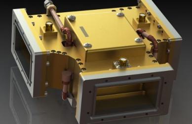
3.4 Waveguide RF Isolators
Waveguide isolators are the preferred choice in many high-power radar and SATCOM systems, where extremely low insertion loss and very high average or peak power are required. These RF isolators use ferrite elements inside a rectangular waveguide, often combined with high-power loads.
In applications such as C-band, X-band, Ku-band and Ka-band earth stations, engineers often put a high-power waveguide isolator directly at the output of the transmitter chain before the antenna feed.
Between these mechanical formats, RF isolator manufacturers can cover frequency ranges from around 20 MHz up to well beyond 40 GHz, with options for narrowband, wideband and ultra-wideband RF isolators.
4. Where Are RF Isolators Used?
Because they solve the universal problem of reflected power, RF isolators appear in almost every serious RF and microwave system. Below are some of the most common application areas.
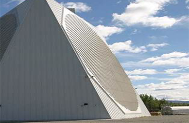
4.1 Radar Systems (L-band to Ka-band)
In pulsed radar, reverse power can easily destroy power amplifiers or degrade pulse shape. Engineers place microwave isolators between the PA and the circulator, or between frequency conversion stages, to:
- Protect PAs from load mismatch when the antenna VSWR is high
- Improve pulse fidelity and reduce ringing caused by reflections
- Suppress feedback that might cause spurious oscillations
4.2 Satellite Communication (SATCOM)
On satellite gateways and VSAT terminals, RF isolators are used throughout the up- and downlink chains: at the output of solid-state PAs, near up-converters, and inside LNB and BUC modules. Here, the RF isolator:
- Protects expensive high-power amplifiers and mixers
- Improves intermodulation performance by stabilizing impedance
- Helps maintain compliance with spectral emission masks
4.3 5G / 6G Radio Units and Small Cells
In 5G and future 6G deployments, RF front-ends are dense and highly integrated. Compact microstrip RF isolators and SMT isolator/circulator hybrids are used to:
- Protect integrated PAs and LNAs on the same board
- Reduce coupling between closely packed RF channels
- Improve EVM, ACLR and overall system linearity
4.4 Test & Measurement Equipment
RF isolators are also standard accessories in RF laboratories. Engineers connect coaxial RF isolators to protect:
- Spectrum analyzers and receivers against over-power
- Signal generators from reflections when driving difficult loads
- Vector network analyzers during high-power swept tests
4.5 Medical RF and Scientific Equipment
MRI systems, scientific accelerators and RF heating systems often include customized microwave isolators to protect high-power amplifiers and to ensure precise, repeatable field conditions. In these cases, reliability and thermal management are just as important as isolation and insertion loss.
5. Key RF Isolator Performance Parameters
When you compare different RF isolator manufacturers or evaluate a datasheet, you will see a familiar set of parameters. The most critical are:
| Parameter | What It Means | Why It Matters |
|---|---|---|
| Frequency range | The operating band (for example, 8–12 GHz for X-band). | Must cover your system band with margin for drift and tolerances. |
| Insertion loss | Forward path loss through the RF isolator, usually in dB. | Lower insertion loss means higher system efficiency and less PA headroom required. |
| Isolation | Attenuation in the reverse direction, in dB. | Higher isolation gives better protection and a more stable source environment. |
| VSWR / return loss | How well the RF isolator presents 50 Ω at each port. | Good VSWR minimizes reflections, especially when devices are cascaded. |
| Power handling | Average and peak power, sometimes CW and pulsed ratings. | Critical for radar transmitters, high-power links and industrial RF systems. |
| Operating temperature | Specified temperature range for full performance. | Important for outdoor, aerospace and defense environments. |
For broadband and ultra-wideband systems, it is also important to look at how insertion loss and isolation vary across the band. A well-designed broadband RF isolator maintains low loss and high isolation across the entire operating range instead of just at the center frequency.
6. RF Isolator vs RF Circulator
RF isolators and RF circulators are closely related ferrite devices. In fact, many RF isolators are built from a three-port circulator with one port terminated in a matched load. However, from a system designer’s perspective, they serve slightly different roles.
| Feature | RF Isolator | RF Circulator |
|---|---|---|
| Ports | Two ports | Three (or more) ports |
| Function | One-way transmission, protects source from reflections | Routes RF power cyclically from port 1→2→3→1 |
| Typical use | Behind amplifiers, oscillators, frequency converters | TR modules, duplexers, routing between TX/RX/antenna |
| Internal structure | Often a circulator with internal termination | Ferrite junction with three external ports |
In many radar or SATCOM systems you will see both: a high-power RF circulator used as a duplexer, followed by a separate RF isolator to give additional protection and maintain a clean, stable impedance for the transmitter.
7. How to Choose the Right RF Isolator
Selecting the correct RF isolator is much more than just choosing the right frequency band. Buyers and design engineers should walk through the following checklist before finalizing a part number or a custom design with an RF isolator supplier.
7.1 Define Frequency Band and Bandwidth
Start with the center frequency and bandwidth of your RF system. Is it a narrowband L-band telemetry link, a broadband X-band radar, or a multi-octave receiver front-end? The broader the band, the more challenging the design and the more important it is to work with an experienced microwave isolator manufacturer.
7.2 Clarify Power Levels and Waveform
Specify both average and peak power for the RF isolator, as well as duty cycle and pulse width for pulsed systems. For very high peak power or long pulse widths, a waveguide isolator may be required even if the rest of the system is in coax or microstrip.
7.3 Choose the Mechanical Format
Decide whether you need a microstrip isolator, drop-in isolator, coaxial isolator or waveguide isolator. This depends on whether the RF isolator will sit inside a compact module, on a PCB, or in a high-power waveguide run near the antenna.
7.4 Consider Environment and Reliability
Clarify your operating temperature range, shock and vibration, altitude, and any vacuum or space constraints. For mission-critical systems, RF isolator manufacturers can upgrade terminations, magnets and materials to guarantee long-term reliability.
7.5 Ask About Customization and ODM Support
Many projects need more than just a catalog part. Custom RF isolators can optimize footprint, connector orientation, cooling features, extended bandwidth or tighter isolation for your specific design.
Tips:
when you send a request for quotation (RFQ) for RF isolators, include: frequency band, bandwidth, power level (CW and peak), required isolation, maximum insertion loss, operating temperature, preferred format (microstrip, drop-in, coaxial, waveguide) and any special environmental requirements.
8. Why RF Engineers Choose HzBeat for RF Isolators & Circulators
HzBeat focuses on ferrite components across a very wide frequency range, from around 20 MHz up to 200 GHz. For RF isolators and RF circulators, this means you can design entire front-ends and signal chains with one partner instead of mixing suppliers.
Our engineering and manufacturing teams support:
- Miniaturized microstrip isolators and SMT isolator/circulator hybrids for dense 5G and microwave modules
- Ultra-wideband drop-in and broadband RF isolators for flexible, multi-band platforms
- High-power coaxial and waveguide isolators for radar, SATCOM gateways and industrial RF
- ODM customization for long-cycle, high-complexity RF projects
Need help choosing RF isolators for your design?
Share your frequency band, power level and mechanical constraints, and our RF engineers can propose suitable RF isolators, RF circulators and matched component sets.
Contact us: [email protected] · WhatsApp: +86 153 8844 0404
9. RF Isolator FAQ
No. A RF circulator is a three-port device that routes energy from port 1 to 2, 2 to 3 and 3 to 1. An RF isolator is usually a two-port device that only allows one-way transmission and protects the source from reflections. Many RF isolators are internally built from a circulator plus a termination.
Q2. Do I always need an RF isolator after a power amplifier?
Strictly speaking, no. But in most practical RF and microwave systems the load VSWR is not perfect. An RF isolator is cheap insurance against damage and instability, especially in high-power radar, industrial RF heating and SATCOM uplinks.
Q3. Can RF isolators handle very wide bandwidths?
Yes. Modern broadband RF isolators and ultra-wideband microstrip isolators can cover multi-octave bands when correctly designed. This is particularly important for wideband receivers, EW systems and frequency-agile platforms.
Q4. How much isolation is “enough” for a typical RF isolator?
Many standard RF isolators offer 18–23 dB of isolation across the band. For more critical applications, 25–30 dB or additional cascaded stages may be required. The right number depends on how sensitive your upstream device is and how severe the expected mismatch will be.
Q5. Can RF isolators be customized?
Yes. RF isolator manufacturers can customize bandwidth, connectors, mechanical outline, mounting arrangement, termination rating and even the internal junction to match your exact needs. Many long-cycle radar and SATCOM projects use fully customized RF isolators rather than catalog parts.
10. References and Further Reading
- IEEE Transactions on Microwave Theory and Techniques – articles on ferrite devices and non-reciprocal components.
- Artech House – Ferrite Devices for Microwave and Millimeter-Wave Circuits, classic reference for ferrite isolators and circulators.
- Radar and SATCOM system design textbooks discussing practical use of RF isolators and RF circulators.
- HzBeat product pages for microstrip, drop-in, coaxial and waveguide isolators and circulators.
Relateds
About the Author

HzBeat Editorial Content Team
Marketing Director, Chengdu Hertz Electronic Technology Co., Ltd. (Hzbeat)
Keith has over 18 years in the RF components industry, focusing on the intersection of technology, healthcare applications, and global market trends.