How to Test RF Circulators: Key Parameters Explained
Updated on:
Keywords: How to Test RF Circulators, RF circulator testing, RF isolator parameters, insertion loss, isolation
Precision is the language of radio. Testing an RF circulator is more than reading numbers—it's translating how waves move, reflect, and are quietly guided forward. This guide distills the parameters, methods, and pitfalls so your measurements are repeatable, comparable, and production-ready.
Why Testing Matters
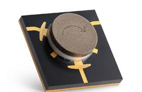
RF circulators are non-reciprocal three-port devices that steer power in one direction (Port 1 → Port 2 → Port 3 → Port 1). In transmit/receive chains, they protect the PA, stabilize matching, and ensure isolation between stages. Any degradation—excess insertion loss, poor return loss, insufficient isolation—translates to heat, reduced efficiency, spurs, and even PA failure.
Robust testing provides three outcomes: (1) acceptance (does the unit meet datasheet limits?), (2) diagnosis (if not, which parameter fails and why?), and (3) traceability (consistent setups across temperature and power). Because results are S-parameter-based, a calibrated VNA workflow is the de-facto standard for meaningful comparisons.
Key Parameters & Definitions
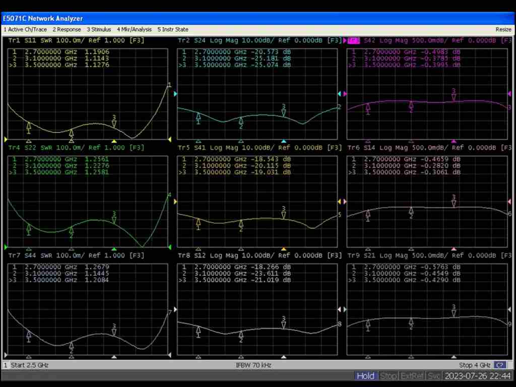
At microwave frequencies, S-parameters describe the relationship between incident and reflected waves at each port. For a 3-port device, you evaluate forward transmission (e.g., S21, S32, S13 for the three forward paths), reverse leakage (e.g., S12), and return (S11, S22, S33).
| Parameter | What It Means | How It’s Measured | Typical Targets* |
|---|---|---|---|
| Insertion Loss (IL) | Loss on the forward path (e.g., Port 1→2). Lower is better. | VNA magnitude of S21 (dB), after SOLT calibration. | ≤ 0.3–0.5 dB (L–X band); ≤ 0.7–1.0 dB (Ku/Ka/F band) |
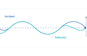
| Isolation | Impedance match at each port (reflection). | From S11, S22, S33; VSWR = (1+|Γ|)/(1−|Γ|). | RL ≥ 14–20 dB (VSWR ≤ 1.5–1.22) |
| Return Loss / VSWR | Impedance match at each port (reflection). | From S11, S22, S33; VSWR = (1+|Γ|)/(1−|Γ|). | RL ≥ 14–20 dB (VSWR ≤ 1.5–1.22) |
| Bandwidth | Frequency span meeting all specs (IL/Isolation/VSWR). | Sweep across band; compute passband mask. | ±10–20% typical; ultra-wideband variants exceed this |
| Power Handling | Max CW/peak power without degradation or thermal runaway. | CW & pulsed power tests with detectors/loads; monitor ΔIL and Δtemp. | 10–200 W CW typical (package-dependent); higher for waveguide |
| Temperature Stability | Performance drift over –55°C to +85°C (or custom range). | Thermal chamber + VNA; log IL/Isolation vs. T. | ΔIL ≤ 0.2 dB; Isolation drift ≤ 2–3 dB across range |
*Targets vary by frequency band, package (microstrip/drop-in/coaxial/waveguide), and ferrite/magnet design.
Tips:
For three-port circulators, always map the “forward” path for each orientation. If Port 1→2 is forward, then Port 2→3 and Port 3→1 must also meet IL targets.
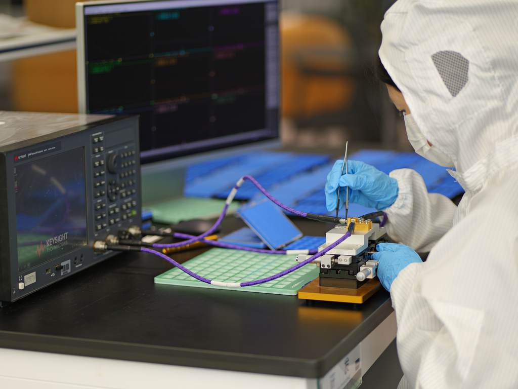
VNA-Based Test Methods
1.Calibration & Reference Plane
Perform SOLT calibration at the cable ends. For waveguide devices, apply TRL/SSLT with waveguide standards. Establish the reference plane at the DUT connectors or launch transitions; for microstrip/drop-in, use test fixtures and de-embed fixture effects.
- Use phase-stable low-loss coax and torque wrenches.
- Strain-relieve cables to avoid drift during sweeps.
- Verify calibration with a known standard or golden sample.
2.Measuring IL, Isolation, and Return
With a two-port VNA, measure one forward path at a time. Rotate connections and terminate the unused port. Measure S21 (IL), S11 (return), and S12 (isolation). Use narrow IFBW and averaging when probing deep isolation.
3.Bandwidth Computation
Create a limit mask (IL ≤ X dB, Isolation ≥ Y dB, RL ≥ Z dB). The bandwidth is the contiguous span where all three are satisfied. Export .s2p/.s3p and compute in post if needed.
4.Power & Temperature Tests
- Power Handling: Apply rated CW/pulsed power with a directional coupler and high-power load. Monitor ΔIL/ΔIsolation and case temperature.
- Thermal Sweep: Measure at –40°C and +85°C (or your spec). Allow soak; look for IL growth and isolation drift.
Interpreting Results & Tolerances
1.If IL is high
- Check calibration drift and cable/connector integrity; re-torque.
- For microstrip/drop-in, inspect launches, via fences, ferrite bias.
- At Ku/Ka/F, conductor/dielectric losses magnify; confirm materials.
2.If Isolation is low
- Confirm port rotation/directionality; mis-porting is common.
- Ferrite bias or gap tolerances reduce non-reciprocity; review magnet stack and tuning.
- Fixture resonances can couple reverse energy; de-embed fixtures.
3.If VSWR is poor
- Inspect connectors/flanges/gaskets and torque values.
- De-embed fixture launches; refine grounding and via fences.
- Use the Smith chart to visualize mismatch and guide matching steps.
Production Hint:
In mass test, store both magnitude and phase of S-parameters. Phase stability flags hidden issues (e.g., loose launch, partial demag) that magnitude alone may miss.
HzBeat Lab Insight
To ensure repeatability across packages and bands, HzBeat uses automated VNA sequences and pass/fail masks aligned to each product family:
Microstrip Circulators — compact, low-loss designs for phased arrays and 5G backhaul.
Coaxial Circulators — broadband, ruggedized connectors for lab/field use.
Waveguide Isolators — high-power, low-loss options for Ku/Ka to D/F bands.
Each unit’s test report includes IL/Isolation/Return across the band, temperature spot checks, and, where applicable, power soak results. We preserve the exact test setup (cal kit, cable set ID, chamber profile) so your qualification can mirror ours.
Common Mistakes & Troubleshooting
- Forgetting the third-port termination: The unused port must be terminated; otherwise isolation/IL readings distort.
- Ignoring the reference plane: Adapters after calibration skew IL; cal at the closest point or de-embed.
- Too wide IFBW at deep nulls: Narrow IFBW and average for isolation > 25–30 dB.
- Fixture radiation at mmWave: Shield fixtures and shorten launches at Ka/F bands.
- Insufficient thermal soak: IL drift can appear minutes after power—log until stable.
FAQ
Q1: Do I need a 3-port VNA?
Not necessarily. A 2-port VNA can characterize a circulator by rotating connections and correctly terminating the unused port.
Q2: How do I specify bandwidth?
Define the passband where IL ≤ X dB, Isolation ≥ Y dB, and RL ≥ Z dB simultaneously. In production, use masks to count contiguous bins that pass all three.
Q3: How does temperature affect results?
Ferrite properties and magnet bias shift with temperature; expect small IL increases and isolation drift at extremes. Validate at –40°C and +85°C (or your own spec).
Q4: What about phase?
For phased arrays and mixers, insertion-phase flatness and port-to-port phase balance matter. Capture phase in S-parameter logs and set limits if your system is phase-sensitive.
References
- Keysight Technologies, S-Parameters and Two-Port Network Measurements, Application Notes (general VNA practice).
- Keysight E5080 Series Help, Measurement Parameters: S-Parameters.
- Choma, J., Scattering Parameters—Concept, Theory, and Applications.
- Microwave engineering textbooks covering multi-port S-parameters and non-reciprocal devices.
Relateds
About the Author

HzBeat Editorial Content Team
Sara is a Brand Specialist at Hzbeat, focusing on RF & microwave industry communications. She transforms complex technologies into accessible insights, helping global readers understand the value of circulators, isolators, and other key components.