High-Power RF Isolators and Circulators for Modern Communication Systems
Updated on:
Keywords: RF circulator, RF isolator, high-power, ferrite, microwave, waveguide, coaxial, drop-in, SMT, low insertion loss, isolation, VSWR, duplexing, PA protection, 5G, SATCOM, radar, Ka-band, Ku-band
Introduction
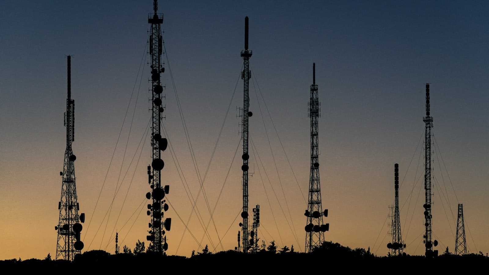
Modern communication systems are simultaneously pushing higher power, wider bandwidth, and tighter spectral coexistence. As networks move through 5G‑Advanced toward early 6G thinking, RF front‑ends must survive tougher mismatch conditions and increasingly dynamic beam‑forming states—without sacrificing linearity or uptime. In this reality, non‑reciprocal devices—isolators and circulators—are no longer optional. They silently protect power amplifiers (PAs), maintain stability under VSWR excursions, and help preserve receiver sensitivity by containing reverse energy.
This article provides an engineering‑first, hands‑on path to designing, testing, and deploying high‑power isolators and circulators. We clarify the specs that truly matter, outline a lab validation plan you can run this week, and convert lessons learned into a practical deployment checklist for base stations, SATCOM gateways, airborne/maritime radar, and test & measurement rigs.
1) Principles: What Non‑Reciprocity Buys You
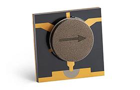
A three‑port circulator routes energy 1→2, 2→3, 3→1 using magnetically biased ferrites that break time‑reversal symmetry for traveling waves. Terminating one port with a matched load yields the familiar two‑port isolator, which passes forward power with minimal insertion loss (IL) while absorbing reverse power. Practical behavior depends on ferrite composition, resonant geometry (junction, stripline, microstrip, waveguide), and impedance‑matching networks. When properly selected and integrated, these parts enable duplexing, protect PAs and LNAs, and improve coexistence.
In high‑power contexts, the same device must also be thermally honest: the tiny forward loss and any reverse dissipation turn into heat. That heat must move cleanly into the chassis/plate/air path, or specs that look ideal on paper will drift on the bench and fail in the field.
2) Form Factors & Integration Styles
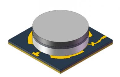
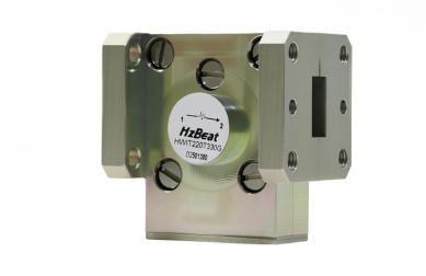
Waveguide devices dominate at high microwave/millimeter‑wave frequencies and high CW/peak power; they provide excellent IL and isolation but are physically larger and require precise flange alignment and torque control. Coaxial parts balance power handling with convenience—popular in base stations, SATCOM terminals, and many radar subsystems. Drop‑in (stripline/microstrip) enables the tightest co‑design of RF/thermal mechanics inside compact modules. SMT/SMD devices address arrays and dense electronics when power levels permit.
3) Specifications that Move the Needle
- Frequency & Bandwidth — From S/L/C/X to Ku/Ka; ensure flat performance across the entire operational band and temperature range.
- Insertion Loss (IL) — Every 0.1 dB matters to EIRP, ACPR, and thermal headroom. Waveguide often wins the IL race.
- Isolation (ISO) — Reverse power rejection under worst‑case mismatch protects PAs and avoids RX desensitization.
- Return Loss / VSWR — Good matching reduces ripple and internal standing waves; check at all ports and fixtures.
- Power Handling — CW and peak under declared VSWR and duty cycle (radar pulses, crest factors, multicarrier loading).
- IMD & Linearity — Verify P1dB/PSAT and IMD with two‑tone/multitone testing; non‑reciprocal devices should not be the bottleneck.
- Thermal Resistance — Quantify case‑to‑ambient and heat‑spreader paths; validate with thermocouples under stress.
- Magnetic Field Tolerance — Bias stability vs. ambient fields and nearby magnets/motors/ferrites.
- Size, Mass, Mounting — Shock/vibration survivability, service access, torque windows, corrosion protection.
- Environmental Reliability — Temperature/humidity/salt‑fog/altitude; ensure finishes and seals hold up in climate extremes.
Tips:
Before you freeze BOM, run a 3‑number check: IL ≤ target across band & temperature; ISO ≥ requirement at band edges and hot; Power rating ≥ PA peak with ≥2 dB margin.
4) Co‑Design with the RF Chain
Non‑reciprocal devices interact with matching networks, duplexers/filters, LNAs, and PA output combiners. Adopt co‑design: select parts early, import S‑parameters into your system model with realistic fixtures, and iterate RF layout, mechanical fastening, and thermal paths in lock‑step.
- Layout/Grounding — For drop‑in/SMT, protect ground integrity and minimize via inductance at ports. Keep high‑di/dt edges away from ferrites.
- Connectors/Flanges — For coaxial/waveguide, maintain cleaning/torque SOPs. A perfect device cannot outrun a poorly torqued connector.
- Thermal Architecture — Provide copper coins/heat spreaders, TIM pads, ducted airflow or cold plates. Log delta‑T during bring‑up.
- Telemetry Hooks — Add temp sensors near the device and directional couplers for forward/reverse power; derate PA drive under alarms.
5) Test & Validation: Lab‑Grade Confidence
A rigorous plan builds confidence before field trials. Start with calibrated S‑parameter measurements (TRL/SOLT as appropriate) and move toward power and thermal stress, mismatch survivability, and environmental cycling. Validate connector/flange repeatability with multiple mate/demate cycles.
| Parameter | Typical Target | Acceptance in Context |
|---|---|---|
| Insertion Loss | ≤ 0.35 dB | Across band & temperature; de‑embed fixtures |
| Isolation | ≥ 23 dB | Maintain at edges and hot; monitor drift |
| VSWR | ≤ 1.25:1 | All ports; with final mechanical stack‑up |
| Power (CW) | Rated + 2 dB | Under 1.5:1 VSWR, continuous operation |
| IMD (2‑tone) | ≤ −120 dBc | For multicarrier cellular links |
| Thermal Rise | ≤ 35 °C @ rated CW | Steady‑state with final heatsink/airflow |
Mismatch Rotation: Exercise 1.2:1–3:1 VSWR with full 360° phase rotation at representative power. Confirm no arcing, no irreversible drift, and stable temperatures. Log events and capture S11/S22, IL/ISO vs. frequency/temperature.
6) Reliability, Power & Thermal, and Compliance
- Headroom — Carry ≥2 dB extra capability over worst‑case PA envelope to absorb reflections, weather, and manufacturing spread.
- Reverse‑Energy Sink — For isolators, ensure internal loads dissipate worst‑case reverse power with clean thermal paths and no outgassing.
- Airflow Management — Avoid hot recirculation pockets; guide flow across spreaders, not around them.
- Standards — Depending on end‑use, consider MIL‑STD‑810 (environmental), DO‑160 (aviation), ingress ratings, and RoHS/REACH.
- Maintainability — Tool access, visible torque labels, corrosion‑resistant hardware; track connector wear in preventative maintenance.
7) Deployment Playbook: From Pilot to Scale
- Freeze Requirements — Band plan, PA CW/peak, duty cycle, VSWR envelope, climate, mechanical constraints.
- Shortlist Devices — Waveguide vs. coax vs. drop‑in vs. SMT with S‑parameters and thermal notes in hand.
- Prototype Bench — Calibrated IL/ISO/VSWR across temperature; CW/pulsed sweeps; mismatch rotation; connector repeatability.
- System Integration — Co‑design matching and heatsinking; verify duplexing with real filters/antennas; log telemetry thresholds.
- Pilot Field Trial — Limited sites, diverse climates; instrument forward/reverse power and temperature sensors.
- Reliability Gate — Environmental cycling, vibration/shock, corrosion checks; MTBF modeling with real stress profiles.
- Scale‑Out — SOPs for torque/cleaning, NOC alarms, spares and RMA pathways, installer training.
8) Use Cases
5G / 5G‑Advanced Base Stations — Massive‑MIMO arrays and multiband nodes rely on isolators to protect PAs when beams steer into non‑ideal impedances and when combiners create complex interactions. Low IL and high ISO preserve linearity budgets and prevent receiver desensitization.
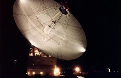
SATCOM Uplinks & Gateways — Ku/Ka uplinks run significant power through long waveguide runs. Robust isolators keep TWTAs/SSPAs safe under cable/antenna faults or weather‑induced mismatch. Temperature/vibration extremes magnify the importance of mechanical fastening and thermal margin.
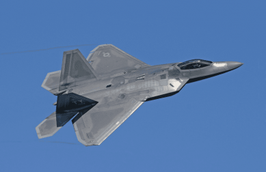
Airborne & Maritime Radar — Pulse power and duty cycles stress peak ratings; circulators enable compact duplexing and protect T/R modules under icing, salt‑spray, and transients. Qualification must include vibration spectra and altitude/pressure effects.
Test & Measurement Racks — Isolators stabilize power sweeps and multi‑tone tests so amplifiers remain linear and measurements reflect the DUT, not rack‑level reflections.
9) FAQ
Q1. How do I choose between an isolator and a circulator? Use an isolator when you must protect upstream equipment from reverse power or stabilize a link under mismatch. Choose a circulator when you also need directional routing—e.g., duplexing on a shared antenna or splitting/combining beam‑forming paths.
Q2. What is a realistic IL target for high‑power devices? In microwave bands, 0.2–0.4 dB is common for quality hardware, with waveguide often at the low end. Every 0.1 dB saved is meaningful for EIRP and thermal headroom.
Q3. How much isolation is “enough”? Application‑dependent, but ≥20 dB across band is a pragmatic baseline for many high‑power systems. Ensure minimums hold at hot temperatures and band edges.
Q4. Can SMT circulators serve high‑power nodes? They are excellent for compact arrays and moderate power. For macro‑level CW/peak power, coaxial or waveguide commonly dominate due to thermal and breakdown headroom.
Q5. What field failures occur most often? Poor connector torque and contamination, inadequate heatsinking, and underestimating reverse power under severe VSWR. Salt‑fog and humidity drive corrosion and dielectric absorption drift without proper sealing/finishes.
10) References
- Pozar, D. M., Microwave Engineering, Wiley.
- Collin, R. E., Foundations for Microwave Engineering, Wiley‑IEEE.
- Rizzi, P. A., Microwave Engineering: Passive Circuits, Prentice Hall.
- Selected vendor application notes and device datasheets for waveguide/coax/drop‑in/SMT circulators and isolators.
Relateds
About the Author

HzBeat Editorial Content Team
Marketing Director, Chengdu Hertz Electronic Technology Co., Ltd. (Hzbeat)
Keith has over 18 years in the RF components industry, focusing on the intersection of technology, healthcare applications, and global market trends.