RF Circulator and Isolator Manufacturing Explained
Updated on:
Keywords: RF circulator, RF isolator, RF circulator factory, RF circulator and isolator manufacturing, ferrite isolator, microstrip circulator, drop-in circulator production, waveguide isolator, broadband RF components.
1. Role of RF Circulators and Isolators
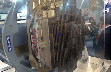
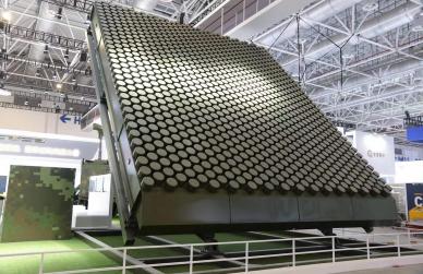
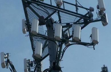
From 5G radios to satellite ground stations and phased-array radars, RF circulators and RF isolators quietly safeguard power amplifiers, tame reflections, and route energy with surgical precision. This in-depth guide opens the doors of an RF circulator factory—a modern to show how China RF supplier HzBeat turns ferrite physics into mass-manufactured reliability. We cover materials, machining, biasing, assembly, tuning, testing, quality systems, OEM/ODM, and the innovation pipeline for broadband RF components with low insertion loss and high isolation.
RF circulators are three-port non-reciprocal devices: power entering port 1 exits port 2, port 2 to 3, and port 3 to 1. RF isolators are two-port variants that strongly attenuate reverse signals, protecting power amplifiers and stabilizing transmitter chains. In practice, they reduce standing waves, improve VSWR, and protect LNAs from overload in T/R modules. For 5G FR1/FR2, SATCOM, EW, and industrial microwave systems, the winning combination is low insertion loss, strong isolation, thermal robustness, and stable performance across temperature and power.
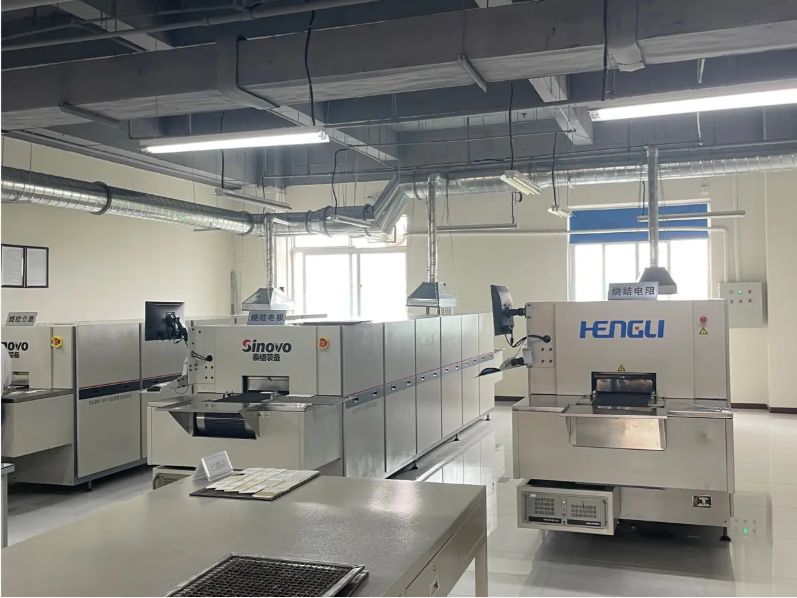
2. Inside a Modern RF Circulator & Isolator Factory
An RF circulator factory typically divides production into controlled zones: ferrite material lab, precision machining, clean assembly, magnetization/biasing, tuning, and automated test. As a China RF supplier, HzBeat runs cross-functional engineering teams—RF/microwave, materials, machining, and QA—to maintain performance consistency from 20 MHz up to 40 GHz (and beyond for waveguide parts). Digital travelers tie BOM and routing to SPC dashboards so yield drift is caught early.
- Ferrite Lab: Garnet-based ferrites are mixed, pressed, sintered, ground and lapped. Magnetic and dielectric constants are characterized versus temperature and frequency.
- Machining: CNC mills/EDM cut housings with tolerances in tens of microns; flatness and parallelism directly affect insertion loss and isolation.
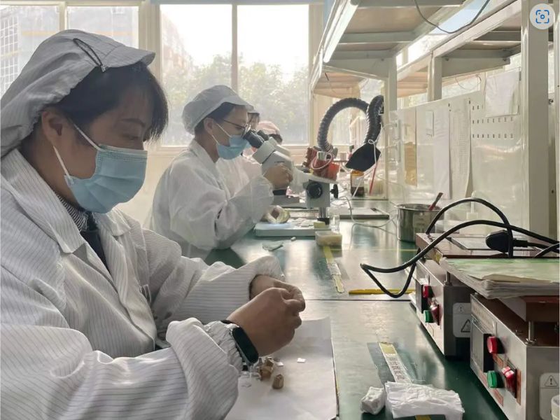
- Clean Assembly: Microstrip/drop-in stacks are assembled with adhesives, spacers, and matching networks; ESD and FOD controls are enforced.
- Magnetization/Biasing: Permanent magnets set the operating point for non-reciprocity, with demag margins validated across worst-case temperature.
- Tuning & Test: Vector Network Analyzers (VNAs) sweep S-parameters; automated scripts gate pass/fail on low insertion loss, isolation, return loss, and bandwidth.
3. Manufacturing Process (Step-by-Step)
3.1 Materials & Pre-Process
Ferrite Selection: For RF isolator and RF circulator cores, garnet ferrites (e.g., YIG-family) balance saturation magnetization, linewidth, and loss tangent. Powders are weighed, mixed, pressed, then sintered with a controlled profile to achieve target density and grain structure. Discs are lapped to tight thickness and surface roughness—micron-level variations change resonance and hence insertion loss.
Metals & Plating: Housings use aluminum or copper alloys with optional Ni/Au plating for solderability and corrosion control. Flatness of mating surfaces and via placement for microstrip is verified by CMM and optical inspection.
3.2 Sub-Assembly: Microstrip, Drop-in, Waveguide
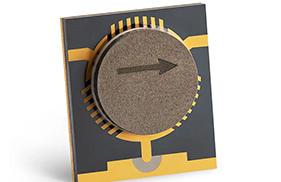
- Microstrip Circulator: A tri-junction microstrip pattern over substrate (e.g., Rogers) sandwiches ferrite discs; magnets provide bias. Chosen for compactness and integration.
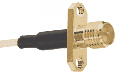
- Drop-in Isolator: Pre-packaged two-port module with matched transitions; favored for robust assembly and field replaceability.
- Waveguide Circulator/Isolator: For Ka-band and up, features machined cavities/coupling elements; excellent power handling with low loss.
3.3 Magnetization & Bias Stabilization
Permanent magnets are sized to bias ferrites at the design operating point while leaving demagnetization margin across temperature extremes (e.g., −40 °C to +85 C). For high-power RF isolators, thermal paths and magnet temperature coeffs are modeled to prevent drift that would degrade isolation or raise VSWR.
3.4 Tuning, Characterization & Data Logging
Tuning shims and alignment screws peak isolation and bandwidth. VNAs sweep S11/S21/S31 (circulator) or S11/S21 (isolator). Typical targets for a broadband RF circulator might be insertion loss < 0.25 dB, isolation > 20 dB, and return loss > 15 dB, depending on band and format. Pass/fail plus full traces are stored to a lot traveler for end-to-end genealogy.
| Type | Band (typ.) | Insertion Loss | Isolation | Notes |
|---|---|---|---|---|
| Microstrip Circulator | 2–18 GHz | < 0.25 dB | > 20 dB | PCB-integrated, light weight |
| Drop-in Isolator | 4–26.5 GHz | < 0.30 dB | > 22 dB | Rugged module, easy field swap |
| Waveguide Circulator | 18–40+ GHz | < 0.35 dB | > 25 dB | High power, low loss |
4. Quality, Reliability & Compliance
Beyond S-parameters, factories implement environmental and mechanical validation: thermal cycling, vibration, drop, salt-fog (when needed), and high-power burn-in. ISO 9001 quality systems, RoHS/REACH compliance, and incoming/outgoing AQL guard consistency. For mission-critical radar and SATCOM, extended qualification— temp soak, humidity bias, and HALT/HASS—is added.
Common Failure Modes & Mitigations
- Thermal Drift: Bias point shifts increase insertion loss or reduce isolation → choose magnets with proper temp coeffs and add heat-spreading paths.
- Mechanical Stress: Warpage changes ferrite contact → precision torque specs, compliant adhesives, and flatness checks.
- Contamination: Particulates raise loss → cleanroom assembly, ultrasonic cleaning, IPC-compliant handling.
- High-Power Lensing: Local heating elevates loss → thermal simulation and copper mass optimization.
5. Customization, OEM/ODM & DFM
As a China RF supplier, HzBeat offers OEM/ODM for microstrip, drop-in, coaxial, and waveguide parts. Design-for-Manufacture (DFM) reviews lock geometry to feasible tolerances; Design-for-Test ensures VNAs and fixtures probe the true performance. Customers provide band, power, size, and environmental targets; the factory returns a spec proposal with low insertion loss and isolation budgets, thermal estimates, and a pilot build plan. For phased-arrays, array-level isolation roll-ups predict cumulative leakage and intermod risks.
Keyword Matrix (selection): RF circulator; RF isolator; RF circulator factory; RF circulator and isolator manufacturing; ferrite isolator; microstrip circulator; drop-in circulator production; waveguide isolator; broadband RF components; low insertion loss; China RF supplier HzBeat; OEM; ODM;
Core terms appear 3–6× across title, lead, H2/H3, body, and figure captions to balance density with readability.
6. Scaling to Volume: Yield, Cost & Lead Time
Volume manufacturing hinges on yield. Key levers:
- Ferrite SPC: Tight control of thickness/flatness reduces re-tuning and scrap.
- Machining Cp/Cpk: Stable cavity/housing tolerances keep isolation peaks centered.
- Automated Magnetization: Inline bias checks prevent out-of-family parts.
- Fixture Strategy: Golden references and calibration intervals keep RF isolator and RF circulator data comparable across lines.
Cost models combine materials (ferrite, magnets, metalwork), touch labor (assembly/tuning), and test time. Lead time improves with common housings, shared substrates, and pooled magnets. HzBeat maintains fast-turn prototyping for NPI while protecting line capacity for high-mix production.
7. Future Materials & Integration
The roadmap blends materials and packaging: lower-linewidth ferrites, hybrid LTCC-ferrite stacks for miniaturization, and thermal interfaces for high-power 5G mmWave/Ka-band. For arrays, co-packaged circulator-PA modules reduce interconnect loss. Data-driven tuning using machine learning flags outliers early and predicts shim choices to hit isolation targets on the first pass.
8. Summary
Manufacturing RF circulators and RF isolators is the art of making physics repeatable at scale. A capable RF circulator factory—a true brings ferrite science, precision machining, clean assembly, robust biasing, disciplined tuning, and thorough test into one rhythm. As a China RF supplier, HzBeat aligns OEM/ODM agility with quality systems so customers ship with confidence—low loss, strong isolation, and dependable reliability.
9. FAQ
Q1. What determines low insertion loss in a ferrite isolator?
A: Ferrite linewidth, disc flatness, cavity tolerances, substrate loss, and magnet bias all contribute. Lapping and fixture-aided tuning keep loss minimal.
Q2. Microstrip vs drop-in vs waveguide—how to choose?
A: Microstrip: light/compact PCB integration. Drop-in: rugged module and quick field replaceability. Waveguide: highest power and lowest loss at mmWave.
Q3. Can HzBeat support OEM/ODM?
A: Yes—band, power, form factor, and environment are engineered to spec with DFM/DFT and pilot lots.
Relateds

About the Author

HzBeat Editorial Content Team
Sara is a Brand Specialist at Hzbeat, focusing on RF & microwave industry communications. She transforms complex technologies into accessible insights, helping global readers understand the value of circulators, isolators, and other key components.