RF Circulator vs Isolator vs Duplexer: Choosing the Right Device for Your Design
Updated on:
Keywords: RF circulator vs isolator vs duplexer, how to choose right rf device, ferrite circulator design, microwave isolator, waveguide duplexer
A complete engineering guide to nonreciprocal RF devices—how they route, protect, and duplex signals; how to read the specs; and how to select the right rf device for radar, satcom, and 5G designs.
Table of Contents
- Understanding Nonreciprocity
- RF Circulators — Design Insights & Applications
- RF Isolators — Protection & Stability
- What About Duplexers? Principle & Differences
- Ferrite Materials & Engineering Considerations
- Key Equations: IL, Isolation, VSWR
- Selection Checklist & Architectures
- Market Insight 2025–2030
- FAQ & Common Mistakes
- References
Understanding Nonreciprocity
Nonreciprocity allows forward transmission with low insertion loss while suppressing reverse propagation. In ferrite-based devices, this arises from gyromagnetic precession under a DC bias—producing direction-dependent phase shifts. Functionally, it lets engineers guide energy from the power amplifier (PA) to the antenna while protecting sensitive receivers from reflections.
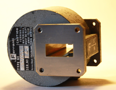
Waveguide isolator (resonance absorption type) showing ferrite and bias topology. Photo © Catslash, Public Domain.
RF Circulators — Design Insights & Applications
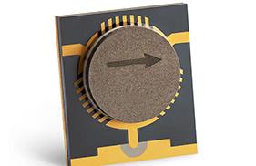
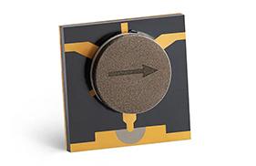
A 3-port circulator routes energy cyclically (Port 1→2, 2→3, 3→1). In radar TR modules and test systems, the circulator acts as a directional traffic director, offering moderate isolation while maintaining low forward loss. Typical long-tail queries include “RF circulator vs isolator difference” and “drop-in circulator for radar TR modules”—both addressed here.
Design Tips (Hzbeat experience)
- Topology: Junction circulators (Y-junction) for compact integration; waveguide for mmWave low loss and higher power.
- Spec reading: Target IL < 0.8 dB, isolation ~18–25 dB across the band, VSWR ≤ 1.25:1 at center frequency.
- Bandwidth: Broadband designs may use multi-section matching and optimized ferrite disks.
Explore: Microstrip Circulators · Drop-in Circulators
RF Isolators — Protection & Stability
An isolator is essentially a circulator with its third port terminated by a matched load. It passes power forward but absorbs reverse power, protecting PAs from load mismatch and suppressing spurs that can degrade EVM/ACLR in wideband links. Long-tail queries such as “low insertion loss microwave isolator” and “broadband isolator frequency range” map directly to spec sheets.
Design Tips (Hzbeat experience)
- Placement: At PA output for mismatch tolerance; may combine with couplers for monitoring.
- Thermals: Ensure the termination load path is well-cooled under worst-case reflected power.
- Linearity: Good matching reduces desense paths into Rx front-ends.
Explore: Coaxial Isolators · SMT Isolators
What About Duplexers? Principle & Differences
A duplexer enables simultaneous transmit/receive through one antenna by frequency separation (distinct TX/RX filters) with high port-to-port isolation. This is essential in FDD systems (e.g., cellular, many satcom links).
| Characteristic | Duplexer Considerations | Why it matters |
|---|---|---|
| Isolation (Tx↔Rx) | Often > 60 dB for robust receivers | Prevents TX leakage into LNA, preserves sensitivity |
| Insertion Loss | 0.5–1.2 dB per branch common | Protects link budget |
| Filter Selectivity | Steep skirts, low ripple | Limits adjacent-band interference / IM products |
| VSWR | < 1.25:1 preferred | Minimizes mismatch loss and PA stress |
Ferrite Materials & Engineering Considerations
Ferrite composition (e.g., YIG-like garnets vs spinel ferrites) and bias strength govern saturation magnetization, linewidth, and temperature stability—directly impacting insertion loss, isolation flatness, and power handling. Designers also tune pole-piece geometry and dielectric loading to optimize field uniformity and impedance matching. For mmWave waveguide parts, high-Q structures minimize conductor loss; for microstrip/SMT, compact packaging and PCB stack-up dominate size and yield.
- Materials: Target low FMR linewidth for low loss; confirm Curie temperature margins for environment.
- Bias: Stable bias over temperature; consider magnet aging and vibration.
- Integration: Drop-in vs microstrip vs waveguide depend on power and frequency budget.
Key Equations: IL, Isolation, VSWR
- Insertion Loss (dB): IL = -10·log10(Pout/Pin)
- Return Loss (dB): RL = -20·log10(|Γ|); with Γ = (ZL - Z0)/(ZL + Z0)
- VSWR: VSWR = (1 + |Γ|) / (1 - |Γ|)
- Isolation (dB): Ratio of reverse to forward power; verify across band & temperature.
Engineering note:
for modulated signals, consider group delay and amplitude ripple—both influence EVM/ACLR even if IL and isolation meet datasheet numbers.
Selection Checklist & Architectures
Decision checklist
- Frequency plan: Same-freq TDD → Circulator; simultaneous FDD → Duplexer.
- Isolation target: If Rx sensitivity requires > 60 dB, Duplexer is mandatory.
- PA protection: Add an Isolator at PA output for mismatch & hot-switching robustness.
- Size / integration: SMT/microstrip for compact modules; waveguide for high power / low loss.
Typical architectures
- Radar TR (TDD): PA → Circulator → Ant, echo → LNA.
- 5G / Satcom (FDD): PA → Duplexer(TX) → Ant; Ant → Duplexer(RX) → LNA.
- High-power TX: PA → Isolator → Ant (plus monitoring coupler).
- Hybrid: Circulator + Filters to increase isolation where space allows.
Need concrete parts?
See Microstrip Circulators, Coaxial Isolators, and Waveguide Isolator. Custom frequency, ports, and dimensions available.
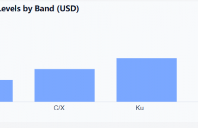
Market Insight 2025–2030
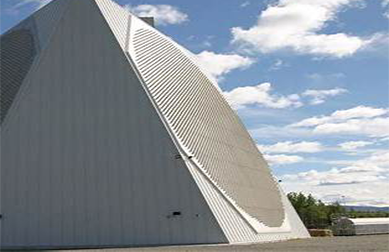
Nonreciprocal RF components remain essential across radar, satcom, and broadband infrastructure. Industry analyses point to steady growth in high-frequency circulators and isolators driven by mmWave links, phased arrays, and compact front-ends. Demand concentrates in bands from S/ C/ X to Ku/ Ka, with renewed interest in E-band and beyond for backhaul and sensing.
FAQ & Common Mistakes
Can a circulator replace a duplexer?
In same-frequency, time-division systems, a circulator can functionally replace a duplexer for antenna sharing. For simultaneous, different-frequency systems (FDD), a duplexer is mandatory due to the high TX↔RX isolation and filtering required.
Do I need an isolator if I already use a duplexer?
Often yes. A PA-side isolator adds insurance against mismatch and transients, reducing risk to the PA and lowering desense paths.
Common mistakes
- Assuming “moderate” isolation from a circulator is enough for simultaneous TX/RX — it usually isn’t.
- Ignoring termination thermal limits on isolators; reflected power must be safely dissipated.
- Overlooking group delay ripple in filtered paths; it affects system EVM/ACLR.
References
- R. E. Collin, Foundations for Microwave Engineering, 2nd ed., McGraw‑Hill.
- IEEE Microwave Theory and Techniques (MTT) tutorials on ferrite nonreciprocal devices.
- MDPI Electronics/Sensors special issues on ferrite circulators and isolators (open access).
- NASA Technical Reports on ferrite components and microwave front-ends.
- Verified Market Reports / MarketsandMarkets coverage of RF/microwave component trends.
- 3GPP specs for EVM/ACLR requirements affecting isolation targets.
Ready to prototype?
Tell us your frequency, bandwidth, power, and port geometry — we’ll propose a matched circulator/isolator set.
Relateds

About the Author

HzBeat Editorial Content Team
Marketing Director, Chengdu Hertz Electronic Technology Co., Ltd. (Hzbeat)
Keith has over 18 years in the RF components industry, focusing on the intersection of technology, healthcare applications, and global market trends.