X-Band Microstrip Circulator
Updated on:
Keywords: X-band microstrip circulator,X-band microstrip isolator,8-12 GHz circulator,SMT RF circulator,miniaturized X-band circulator,X-band PCB circulator,SMT isolator supplier,HzBeat
Compact X-band microstrip circulators and microstrip isolators for radar, SatCom, and high-density T/R modules, designed for SMT assembly and long-term production.

1. Why X-Band Microstrip Circulators Matter to Buyers
X-band (typically 8–12 GHz) is the workhorse band for many radar, SatCom, and high-resolution sensing systems. For these platforms, a microstrip circulator or microstrip isolator is often the only practical way to keep the RF front-end compact enough for modern T/R modules, active phased arrays, and airborne or space-limited terminals.
Compared with traditional waveguide or bulky coaxial devices, an X-band microstrip circulator is:
- Much smaller – footprint can be only a few millimetres on the PCB, suitable for dense T/R tiles.
- Compatible with SMT – designed for reflow assembly and pick-and-place, reducing manual labour and rework.
- Cost-efficient at scale – lower assembly cost per channel when you have hundreds or thousands of T/R paths.
- Easier to customise – matching, bandwidth, and port direction can be tuned to your exact 8–12 GHz window.
2. Core Selection Criteria for X-Band Microstrip Circulators & Isolators
When you evaluate an X-band microstrip circulator/isolator for 8–12 GHz projects, most decisions come down to a few practical parameters. A typical RF procurement checklist looks like this:
2.1 Electrical performance window
- Frequency range: does the part cover your exact X-band (for example 8.5–10.5 GHz, 9–10 GHz, or 8–12 GHz full band)?
- Insertion loss (IL): every 0.1 dB matters, especially in low-noise radar receivers and long-range links.
- Isolation: high isolation protects LNAs from reflected TX power and improves clutter performance.
- VSWR / return loss: poor match increases ripple, PA stress, and can complicate system tuning.
2.2 Power, thermal, and environment
- Average and peak power: ensure enough margin over your PA output, including pulse peaks.
- Operating temperature: X-band front-ends in radar and SatCom often specify −40 °C to +85 °C or wider.
- Stability and reliability: important for 24/7 ground stations, airborne platforms, and fielded radar systems.
2.3 Footprint, package, and assembly
- Footprint size: in modern phased arrays, circulators must fit in tight lattices alongside PAs, LNAs, and beamformers.
- SMT compatibility: land pattern, solder mask, and ground stitching must be compatible with your PCB technology.
- Dual-junction vs single-junction: dual-junction often improves isolation and power handling at the cost of size and complexity.
2.4 Supply chain and lifecycle
- MOQ & sample access: can you start with 10–20 pcs, then smoothly ramp to hundreds or thousands?
- Lead time: 4–6-week typical lead times are common for customised microstrip products; buffer for project milestones.
- Customisation roadmap: can the supplier support derivative designs (e.g. X-band microstrip isolators) without restarting qualification?
3. HzBeat X-Band Microstrip Circulator Portfolio (Real Specs)
HzBeat offers a dedicated X-band microstrip family targeting 8–12 GHz radar, SatCom, and high-density RF modules. Below is a simplified view of some standard X-band microstrip circulators and dual-junction variants that buyers typically shortlist for 8–12 GHz projects.
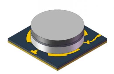
3.1 8.0–12.0 GHz miniaturised microstrip circulators
These parts are single-junction miniaturised microstrip circulators that cover the full X-band from 8.0 to 12.0 GHz, with compact footprints and SMT-friendly construction.
| Model | Freq. (GHz) | Topology | Max IL (dB) | Min Isolation (dB) | Max VSWR | PK / CW Power (W) | Direction |
|---|---|---|---|---|---|---|---|
| HMCTA80T120G-M | 8.0–12.0 | Miniaturised microstrip, “T” junction | 0.9 | 15 | 1.4 | 20 / 5 | Clockwise |
| HMCTB80T120G-M | 8.0–12.0 | Miniaturised microstrip, “T” junction | 0.9 | 15 | 1.4 | 20 / 5 | Counter-clockwise |
| HMCYA80T120G-M | 8.0–12.0 | Miniaturised microstrip, “Y” junction | 0.9 | 15 | 1.4 | 20 / 5 | Clockwise |
| HMCYB80T120G-M | 8.0–12.0 | Miniaturised microstrip, “Y” junction | 0.9 | 15 | 1.4 | 20 / 5 | Counter-clockwise |
These models are well-suited for wideband X-band systems where you want a single part to cover the entire 8–12 GHz range, such as wide-scan phased arrays, multi-mode radar, or reconfigurable SatCom front-ends.
3.2 Narrower-band dual-junction X-band microstrip circulators
For applications that favour lower insertion loss, higher isolation, or higher internal load power, dual-junction X-band microstrip circulators in narrower windows (for example 9–10 GHz or 8.5–10.5 GHz) are often used.
| Model | Freq. (GHz) | Type | Max IL (P1–P2) | Min Isolation (P2–P1) | Max VSWR | PK / CW / Load (W) | Direction |
|---|---|---|---|---|---|---|---|
| HMDHA90T100G-M | 9.0–10.0 | Miniaturised dual-junction | 0.5 dB | 18 dB | 1.25 | 10 / 5 / 1 | Clockwise |
| HMDHB90T100G-M | 9.0–10.0 | Miniaturised dual-junction | 0.5 dB | 18 dB | 1.25 | 10 / 5 / 1 | Counter-clockwise |
| HMDHA85T105G-M | 8.5–10.5 | Miniaturised dual-junction | 0.4 dB | 18 dB | 1.25 | 20 / 10 / 3 | Clockwise |
| HMDHB85T105G-M | 8.5–10.5 | Miniaturised dual-junction | 0.4 dB | 18 dB | 1.25 | 20 / 10 / 3 | Counter-clockwise |
These parts are frequently selected for critical X-band channels where you need a little more margin on IL, isolation, or reflected-power handling than a single-junction part can give — for example, high-duty radar or space-constrained but power-dense front-ends.
4. What This Means for BOM, Assembly, and Total Project Cost
With microstrip, you do not need bulky flanges, adapters, or multiple coax jumpers. A single X-band microstrip circulator drops onto the PCB footprint, soldered in the same reflow as your MMICs. That directly reduces:
- The number of mechanical assembly steps per T/R channel.
- The number of RF connectors and cables per module.
- The risk of human-assembly variability in high-volume builds.
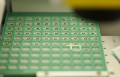
4.1 Stable production in a modern RF laboratory

HzBeat operates an RF production laboratory environment with dedicated workstations, microscopes, and RF measurement equipment. This supports consistent soldering, tuning, and testing of X-band microstrip circulators and isolators. For buyers, this translates into predictable quality and repeatable performance across batches, rather than one-off lab prototypes.
4.2 SMT-friendly design and stable process window
HzBeat’s miniaturised X-band microstrip circulators are designed for surface-mount installation, compatible with standard pick-and-place and reflow profiles. This allows your EMS partner to treat the circulator as just another SMT component — not a special manual-mount part that slows the line or requires exotic handling.
4.3 One supplier, multiple form factors
In many programmes you need a mix of microstrip, drop-in, coaxial, and waveguide circulators and isolators across different frequency bands. Consolidating them with a single supplier reduces qualification overhead, eases documentation, and simplifies long-term lifecycle management.
5. Typical Procurement Workflow for X-Band Microstrip Circulators
A practical X-band project often follows this sequence on the buyer side:
- Early design discussion: share your 8–12 GHz band, power, and mechanical constraints with the supplier’s applications team, including whether you also need an X-band microstrip isolator derivative.
- Sample & evaluation phase: order a small batch (commonly from 10 pcs per model) for evaluation boards, S-parameters, and system integration tests.
- Design freeze: lock in final model(s), direction (CW/CCW), and any special test or screening options.
- Pilot build: run one or more pre-production builds at your EMS or in-house line to validate yield and reflow robustness.
- Volume ramp: step up to larger lots with agreed lead times (for example 4–6 weeks), synchronised with your RF module and system build plans.
When this workflow is handled with a supplier experienced in X-band microstrip circulators and isolators, you significantly reduce programme risk around RF front-end availability.
6. FAQ: X-Band Microstrip Circulators & Isolators for Buyers
Q1. What is the difference between an X-band microstrip circulator and isolator?
A circulator routes power between three ports in sequence (for example Port 1 → Port 2, Port 2 → Port 3, Port 3 → Port 1). An isolator typically terminates one of these ports in a matched load, so that the device only has two usable ports (input and output) while absorbing reverse power.
In microstrip technology, isolators are often derived from the same core platform as circulators, which makes qualification and sourcing much easier — you can base both on the same ferrite and geometry family.
Q2. When should I choose a dual-junction X-band microstrip circulator?
Choose dual-junction when you need one or more of the following:
- Lower insertion loss (for example around 0.4–0.5 dB across a narrower X-band window).
- Higher isolation and/or higher internal load power rating.
- More robustness to mismatch and reflected power in pulsed radar systems.
The trade-off is slightly more complex internal structure and, in some cases, a slightly larger footprint compared with the simplest single-junction parts.
Q3. What MOQ and lead time should I plan for?
For most microstrip circulators and isolators, a reasonable expectation is:
- Lead time: typical production lead times of about 4–6 weeks, depending on volume and customisation level.
For urgent programmes, you can sometimes secure expedited lots if your RF specs are close to an existing, proven platform.
Q4. Can the footprint and land pattern be customised for my PCB?
Yes. For many X-band projects, the supplier can co-design:
- The land pattern and solder mask openings for your specific PCB stack-up.
- Ground via stitching around the body for better isolation and thermal performance.
- Shielding options or mechanical keep-outs if the circulator sits under a module lid.
Sharing your PCB cross-section and assembly guidelines early will help avoid re-spins and accelerate design freeze.
Q5. How do I start a new X-band microstrip circulator / isolator project?
A simple way to start is:
- Pick one or two candidate models in the 8–12 GHz family (for example HMCTA80T120G-M or an HMDH X-band dual-junction model).
- Share your schematic, required band, and PA/LNA power levels with the supplier’s applications team.
- Request S-parameters and a small batch of samples for evaluation.
- Once performance is confirmed, lock in a long-term supply plan covering prototypes, pilot runs, and volume builds.
7. Next Step: Align X-Band Microstrip Circulators with Your Roadmap
Whether you are building a next-generation X-band phased-array radar, a compact maritime SatCom terminal, or a high-density test front-end, the choice of X-band microstrip circulator / isolator directly affects your module size, efficiency, and long-term supply risk.
By basing your design on proven 8–12 GHz miniaturised and dual-junction platforms, you can:
- Keep RF performance and size under tight control.
- Simplify SMT assembly and testing across multiple product generations.
- Secure a stable, scalable supply chain from engineering samples to volume production.
For detailed drawings, S-parameters, or a tailored X-band BOM proposal, please contact your HzBeat representative or use the contact form on the main website.
Relateds


About the Author

HzBeat Editorial Content Team
Sara is a Brand Specialist at Hzbeat, focusing on RF & microwave industry communications. She transforms complex technologies into accessible insights, helping global readers understand the value of circulators, isolators, and other key components.