How to Optimize Your RF Chain Using High-Isolation Isolators
Updated on:
Keywords: RF isolator, high isolation, circulator, VSWR, mismatch loss, PIM, radar, satcom, 5G, mmWave, ferrite isolator, PA protection, waveguide isolator, RF chain optimization
Introduction
RF systems are only as strong as their weakest link—and in high-power or high-frequency environments, reflections and impedance instability can quietly undermine performance. High-isolation isolators solve this by decoupling the source from load mismatches, protecting devices like power amplifiers and low-noise amplifiers from reverse energy.
Whether you’re designing a 5G base station, radar transmitter, or satellite payload, optimizing your RF chain with isolators ensures cleaner signals, longer component life, and higher measurement repeatability.
1. Why High-Isolation Matters
An isolator allows forward power to pass while absorbing any reverse power. The higher the isolation, the better it protects your source. For every 10 dB improvement in isolation, the reverse power that reaches the source drops by 90%. In radar transmitters, a 30 dB isolator can mean the difference between stable output and oscillation.
2. Key Placement Strategies
Where isolators are placed determines their effectiveness:
- PA Output: Protects transmit amplifiers from reflected energy caused by load variations or open circuits.
- T/R Modules: Shields receiver inputs from transient leakage during fast switching.
- LNA Input: Stabilizes input match and prevents feedback oscillation in sensitive receivers.
- Mixers: Reduces conversion ripple and spurious coupling.
- Test Ports: Improves VNA and power meter repeatability in production lines.
3. Balancing Isolation, Insertion Loss & Power
Isolation and insertion loss are two sides of the same coin. High isolation often means longer ferrite paths or tighter bias fields—both add slight loss. Engineers must determine the sweet spot: enough isolation for stability, but minimal IL to preserve gain.
For instance, a 40 W transmitter facing a 4:1 VSWR reflects 14 W. A 20 dB isolator reduces that to 0.14 W—safe for most solid-state amplifiers.
4. Linearity and PIM Reduction
Reverse power distorts active device load lines and worsens linearity. High-isolation isolators stabilize these conditions, lowering Adjacent Channel Power Ratio (ACPR) and improving Error Vector Magnitude (EVM). They also reduce passive intermodulation (PIM) by preventing multi-tone reflections that mix at connectors or cables.
5. Power Handling and Thermal Design
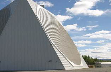
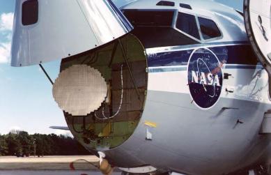
When full reflection occurs, the isolator’s termination must absorb all the reverse energy. In high-power radar or satcom systems, this is nontrivial—waveguide isolators are designed for exactly this. Their metallic body and large ferrite volume act as both heatsink and RF load, safely dissipating energy as heat.
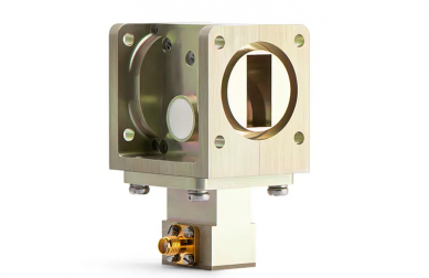
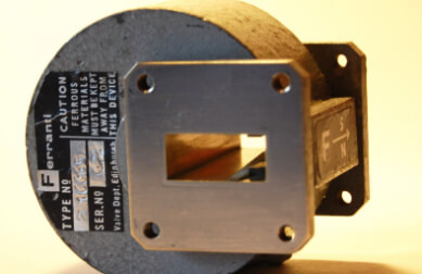
6. Choosing the Right Isolator Type
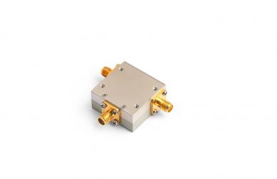
- Drop-in / SMT: Compact for PCB integration; typical ISO ≥ 20 dB, IL ≈ 0.5 dB.
- Coaxial: Versatile and broadband; suited for rack systems and test setups up to 40 GHz.
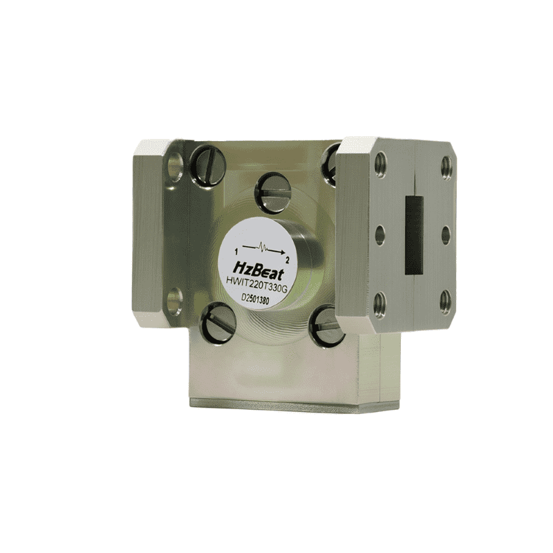
- Waveguide: Handles extreme power and frequencies; minimal IL ≤ 0.2 dB and ISO > 35 dB.
- Cascaded: Two-stage isolators plus pads for ISO > 45 dB when required by system stability margins.
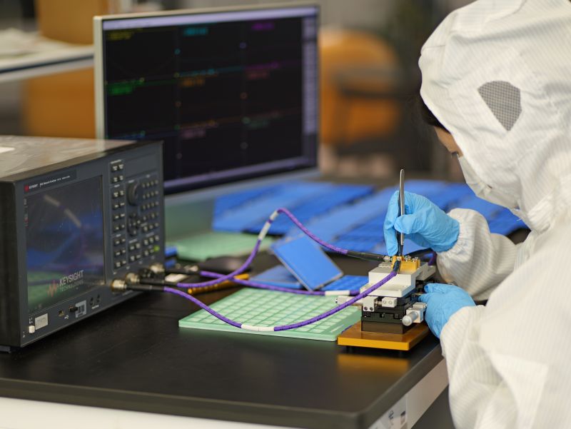
7. Laboratory Optimization & Measurements
During VNA measurements, adding isolators between the DUT and source minimizes ripple and improves calibration accuracy. Even small 0.4 dB IL devices dramatically enhance measurement repeatability. Modern analyzers compensate automatically for known losses, so the gain in stability outweighs minor attenuation.
8. Practical Design Checklist
- Identify high-VSWR nodes using load-pull simulations.
- Determine maximum allowable reflected power for each amplifier stage.
- Select isolators with adequate ISO margin (≥ 6 dB beyond need).
- Check IL contribution to noise figure and gain budget.
- Ensure termination dissipation rating ≥ max reflected power.
- Validate ferrite temperature coefficient stability.
- Use low-PIM connectors and clean assembly practices.
9. Application Scenarios
5G Base Stations
Isolators at PA combiners keep EVM low and mitigate PIM under multi-carrier traffic. Outdoor environmental shifts—humidity, ice, or cable flex—alter antenna impedance; isolators safeguard transmit modules against those variations.
Radar & Satcom Transmitters
Waveguide isolators ensure continuous-wave radar or TWT systems remain stable under full reflection. Their external loads are often convection-cooled or fin-mounted for long-term reliability.
Measurement & Production Lines
Test benches often connect to multiple devices sequentially; one failed unit can reflect and disrupt readings. A simple coaxial isolator between station and DUT prevents crosstalk and instrument damage.
10. Worked Example — Sizing Isolation
A 40 W PA at 4:1 VSWR → 14 W reflected. To limit reverse power below 2 W, need ISO ≥ 8.6 dB + margin 6 dB = 15 dB. Accounting for occasional 6:1 mismatches, 20 dB ISO is preferred. Device should feature IL ≤ 0.5 dB and termination rated for full reflection at 40 W continuous.
11. Integration Pitfalls
- Never underspec termination wattage—design for 100% reflection.
- Include IL in gain/noise budgets; 0.5 dB loss ≈ 11% efficiency drop.
- Account for magnetic bias drift with temperature.
- Regularly inspect connectors to avoid PIM-related degradation.
12. Optimization Workflow
- Simulate and compare system stability with and without isolators.
- Measure S-parameters to confirm ISO across the full band.
- Test termination under worst-case reflection scenarios.
- Apply redundancy for mission-critical radar/satcom systems.
- Document isolation and IL values in QA reports for traceability.
13. Frequently Asked Questions
Q1. Do I need isolators if my antenna is perfectly matched?
Yes. Real environments drift—humidity, corrosion, or temperature shift match conditions. Isolators offer essential insurance.
Q2. What isolation is enough for most RF systems?
20 – 25 dB for medium power; 35 – 45 dB for high-power radar or satcom links.
Q3. Does insertion loss affect performance?
A small 0.5 dB IL slightly lowers efficiency but dramatically increases linearity and reliability.
Q4. Are isolators frequency-dependent?
Yes. Ferrite bias and geometry determine center frequency; broadband types cover multi-octave spans.
Q5. How can I measure isolation accurately?
Use a calibrated VNA and measure S12 from port 2 to 1 with a matched load; verify ISO vs. power and temperature.
Relateds
About the Author

HzBeat Editorial Content Team
Sara is a Brand Specialist at Hzbeat, focusing on RF & microwave industry communications. She transforms complex technologies into accessible insights, helping global readers understand the value of circulators, isolators, and other key components.