K-Band Microwave Circulators and Isolators: Enabling Next-Generation Connectivity
Updated on:
Keywords: K-Band circulator, K-Band isolator, microwave circulator, RF isolator, 18–27 GHz
Between 18 and 27 GHz, compact apertures and high‑throughput radios demand front‑ends that remain linear, stable, and safe under reflections. Circulators and isolators make that possible—enforcing directionality, protecting PAs and LNAs, and enabling concurrent TX/RX paths in phased arrays and backhaul links.
Table of Contents
- At a Glance: Where K‑Band Fits
- Nonreciprocity & Device Physics
- Designing for 18–27 GHz
- Packaging & Integration
- Selection Guide (Engineering Checklist)
- Rain‑Fade & Availability Notes
- Featured HzBeat K‑Band Microstrip
- Applications
- References
Related Products
Waveguide Circulators · Drop-in Circulators · Microstrip Circulators · Coaxial Isolators
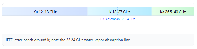
At a Glance: Where K‑Band Fits
K‑band occupies the middle ground between Ku and Ka. Designers leverage its balance of antenna compactness, available spectrum, and manageable rain attenuation. Around 20–24 GHz, link budgets can be favorable for short‑to‑medium‑range backhaul; at the same time, aperture sizes are small enough for airborne payloads and dense tiles. Near 22.24 GHz, the water‑vapor absorption line increases gaseous attenuation and should be budgeted for availability targets at 99.9% and above.
Nonreciprocity & Device Physics
Circulators route power sequentially (1→2, 2→3, 3→1); isolators pass power one way and absorb or reflect the reverse. Ferrite devices exploit a static bias to make permeability a tensor, breaking time‑reversal symmetry. At K‑band, designers must control resonant line width and bias uniformity to maintain isolation without penalizing insertion loss or thermal stability. Nonreciprocal phase progression is engineered by the junction geometry and matching networks so that in the reverse direction power experiences destructive interference and loss, while the forward path remains minimally lossy.
Designing for 18–27 GHz
Insertion loss rises with frequency through conductor/plating losses and ferrite loss tangent; return loss dictates PA load‑pull and LNA stability. Isolation budgets start at 20–25 dB for compact T/R modules, with higher targets for sensitive receivers or early full‑duplex experiments. Bias magnets and ferrite temperature coefficients require environmental screening across corners; self‑biased stacks cut current draw at the cost of adjustability.
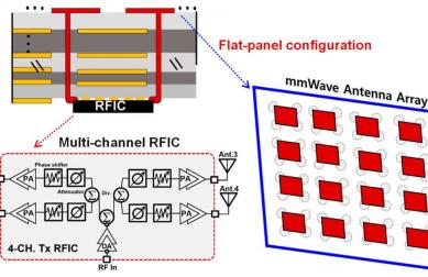
Packaging & Integration
- Waveguide (e.g., WR‑51/WR‑42 near edges): Lowest IL, highest power; favored in Satcom payloads and early PA stages.
- Drop‑in: Compact and tunable; balanced IL/ISO for dense T/R modules with controlled assembly.
- Microstrip / SMT: Maximum density; ideal for tiled arrays—pay attention to ground integrity, bias routing, and EM coupling in the laminate stack‑up.
- Coaxial: Flexible interconnects for test and system interfaces.
Selection Guide (Engineering Checklist)
| Parameter | Target / Rule‑of‑Thumb | Notes |
|---|---|---|
| Frequency Range | Center ± fractional BW (e.g., 22 GHz ± 10%) | Reserve margin for calibration, LO plan, and tolerances. |
| Insertion Loss | < 0.5 dB typical (format‑dependent) | Generally Waveguide < Drop‑in < Microstrip. |
| Isolation | > 20–25 dB | Increase for sensitive receivers or duplex trials. |
| Return Loss | > 14 dB | Improves EVM and PA load tolerance. |
| Power Handling | Specify peak/avg | Thermal path, plating, and bias uniformity matter. |
| Temperature Range | −40…+85 °C (typical) | Screen across corners; track magnet/ferrite tempco. |
| Form Factor | Waveguide / Drop‑in / SMT / Coax | Choose to match module stack‑up and assembly flow. |
| Reliability | Shock, vibe, thermal cycling | Define screens per aerospace/auto standards. |
| Compliance | RoHS/REACH, export controls | Verify program constraints early. |
Rain‑Fade & Availability Notes
Rain attenuation is a dominant availability driver at K‑band. ITU‑R P.838‑3 gives specific attenuation γR = k · Rα (dB/km), where R is rain rate (mm/h) and k, α depend on frequency and polarization. For a path of length L (km), budget Arain ≈ γR · L · r with r an effective path factor from propagation models (see P.618). Add gaseous absorption near 22.24 GHz to the margin where applicable.
Worked example. Suppose 22.5 GHz, horizontal pol., R=50 mm/h, k≈0.10, α≈0.9 (illustrative). Then γR≈0.10·50^0.9≈3.9 dB/km. For L=3 km and effective r=0.8, Arain≈3.9×3×0.8≈9.4 dB. With 2 dB gaseous/other losses and 3 dB engineering margin, design for ~14–15 dB fade reserve.
Coefficients must be taken from ITU‑R P.838‑3 tables; climate statistics from P.837 and path modeling from P.618. Use site‑specific data for final designs.
Featured HzBeat K‑Band Microstrip
For compact, high‑density assemblies, HzBeat’s Microstrip Circulator family includes K‑band capable options. Representative categories and published band coverages include:
Typical Microstrip Circulator
Multi‑band coverage including K‑band (site lists S/C/X/Ku/K/Ka across 2–40 GHz). Ideal for tiled arrays and compact transceivers that require balanced IL/ISO.
K‑band · Compact · Array‑ready
Miniaturized Microstrip Circulator
Published coverage includes K‑band and Ka (site notes C/X/K/Ka across ~5–37 GHz). Designed for space‑limited modules where area and height are tightly constrained.
K‑band · Miniature · High‑density
Band statements above reflect HzBeat public listings at the time of writing; final specs vary by part number and custom options. Please confirm with sales/FAE for program‑specific requirements.
Applications
Satcom: K‑band feeder links with compact terminals; circulators isolate the LNA path and stabilise TX chains under VSWR excursions during rain events.
Automotive/Aerospace Radar: 24 GHz and K‑band SRR niches persist alongside 77–81 GHz LRR; nonreciprocal components limit leakage and preserve FMCW linearity, particularly during fast beam scanning.
5G/6G Backhaul: Short‑hop links where fiber is impractical; device linearity and temperature stability directly set EVM and ACLR, while isolation and match define PA stress and spectral regrowth.
References
- IEEE K‑band definition (18–27 GHz) and 22.235 GHz water‑vapor line context.
- ITU‑R P.838‑3: Specific attenuation model for rain (γR = k·Rα); ITU‑R P.618 (Earth‑space propagation paths) and P.837 (rain climate).
- NASA/NTIA classic studies on 22.235 GHz water‑vapor absorption and gaseous attenuation.
- Microwave Journal: K‑band/WR components for satellite payloads and feeder links.
- Keysight/TI automotive radar notes comparing 24 GHz with 77–81 GHz for resolution and regulatory context.
- HzBeat Microstrip Circulator page: category coverage notes for K‑band capable products.
Relateds

About the Author

HzBeat Editorial Content Team
Marketing Director, Chengdu Hertz Electronic Technology Co., Ltd. (Hzbeat)
Keith has over 18 years in the RF components industry, focusing on the intersection of technology, healthcare applications, and global market trends.