Why RF Isolators and Circulators Are Becoming Essential in 5G and Beyond
Updated on:
Keywords: RF circulator, RF isolator, microwave circulator, microwave isolator, massive MIMO, 5G, TDD, VSWR, PIM, satellite, radar, Ka-band, Ku-band, microstrip, drop-in, coaxial, waveguide, SMT
Introduction
The promise of 5G—capacity, latency, reliability—depends on disciplined RF engineering. In time-division duplex (TDD) radios, massively parallel antenna arrays, and dense urban cells, reflections, mismatch, and interference accumulate. An RF isolator ensures energy flows cleanly away from sensitive stages, while an RF circulator routes transmit/receive power directionally, enabling duplexing on a shared antenna or clean cascading of amplifiers and filters. In short: the non-reciprocal behavior of the RF circulator and the one-way protection of the RF isolator keep high-power power amplifiers (PAs) and low-noise receivers out of trouble—and keep key performance indicators (KPI) stable.
Circulator shunts reflected power; isolator absorbs it.
Protects PA stages & LNAs in massive-MIMO radios.
Mitigates mismatch-induced distortion & PIM exposure.
Enables robust T/R routing with compact RF chains.
1) 5G Architecture: Why Non-Reciprocal Devices Matter
In massive MIMO (64–256T/R), radios combine dozens of transmitters and receivers per sector. Each branch must withstand antenna mismatch, thermal drift, and multi-carrier stress, while maintaining linearity and sensitivity. Here, a circulator provides directional signal flow—TX → ANT, ANT → RX—reducing the probability that reflected energy re-enters the PA or desensitizes the LNA path. A paired isolator adds one-way attenuation for reverse power, acting as a “safety diode” for RF, especially during load transients and VSWR excursions (e.g., wet radomes, damaged connectors).

2) RF Isolator & RF Circulator Basics
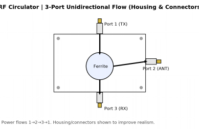
An RF circulator is a three-port, non-reciprocal device that routes power in one direction (1→2, 2→3, 3→1). Terminating one port with a matched load transforms it into an RF isolator with strong reverse isolation. Both rely on a magnetized ferrite puck exhibiting gyromagnetic resonance; biasing sets the preferred direction of propagation and the operating band. Practical microwave circulators/isolators appear as microstrip, drop-in, coaxial, or waveguide packages to span from sub-GHz to Ka-/V-/W-band.
3) 5G & Beyond: Core Use-Cases for the RF Circulator & RF Isolator
3.1 PA protection under high VSWR
Real-world antennas rarely remain perfectly matched. Ice, rain, or installation faults increase VSWR and produce reverse power. A circulator steers that energy to a load; an isolator absorbs it. This prevents PA over-voltage/current events and avoids receiver desensitization.
3.2 Shared-antenna T/R routing (TDD radios)
With TDD base stations, time-multiplexed TX and RX frequently share the same antenna aperture. A circulator implements directional routing with minimal control logic, complementing or replacing active T/R switches. Combined with band-select filtering, it yields robust isolation between TX and RX chains.
3.3 PIM risk mitigation
Passive intermodulation (PIM) from non-linear contacts and assemblies can fold intermods into the receive band, degrading SNR and capacity. Clean mechanical design plus strategic isolator placement reduce the energy that excites such non-linearities and help preserve receiver sensitivity in multi-carrier LTE/NR deployments.
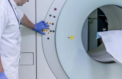
3.4 Multi-band radios, radar, and satcom
Whether it’s C-/X-band phased-array radar, Ku-/Ka-band VSAT terminals, or mmWave small cells, the RF isolator and RF circulator stabilize the chain across temperature, altitude, and power cycling—crucial for link availability and calibration repeatability.
4) Key Specifications & What They Mean
| Parameter | Why it Matters | Typical Targets (sub-6G) | Typical Targets (mmWave) |
|---|---|---|---|
| Insertion Loss | Directly impacts PA efficiency and RX NF | ≤0.3–0.6 dB | ≤0.8–1.2 dB |
| Isolation | Prevents reverse power & desense | ≥20–25 dB | ≥18–22 dB |
| Return Loss / VSWR | Ensures match to adjacent stages | RL ≥ 18–20 dB (VSWR ≤ 1.3) | RL ≥ 14–16 dB |
| Power Handling | Withstands peak/avg PA power & mismatch | 10–200 W avg (use-case dependent) | 2–50 W avg |
| Temperature Range | Outdoor radios, aerospace & thermal cycles | –40 to +85 °C (or higher) | –40 to +85 °C |
| Bandwidth | Accommodates carrier aggregation / TDD bands | 5–20% fractional | 5–10% fractional |
For multi-carrier 5G radios, low insertion loss minimizes PA back-off; high isolation and good return loss keep EVM and ACLR on-spec. In mmWave small cells and backhaul, package parasitics raise loss and reduce isolation margins—careful selection and board layout become decisive.
5) Packages & Bands: From SMT to Waveguide
5.1 SMT / Microstrip (compact devices)
Best where size and assembly flow rule: small-cell radios, IoT gateways, densely packed RF modules. An SMT isolator offers compact one-way protection; an SMT circulator routes signals with minimal footprint. Pay attention to PCB stack-up tolerance and ground stitching around the part for stable isolation.
5.2 Drop-In (broad usage in microwave modules)
Drop-in packages balance performance and integration ease. They suit X-/Ku-band radar and satcom line-ups, where thermal management and screw-down assembly ensure repeatable contact and low PIM risk.
5.3 Coaxial (robust, serviceable)
Coaxial circulator/isolator parts excel in high-power paths and field-serviceable enclosures (e.g., macro radios, test stands). They are often chosen when flexible cabling and connectorized maintenance are required.
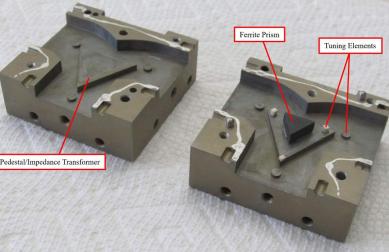
5.4 Waveguide (mmWave, highest power density)
For Ka/V/W-band and high-power radar, waveguide forms deliver the lowest loss and highest isolation. Mechanical precision and magnet biasing accuracy dominate performance and yield.
6) Selection Checklist for Engineers & Buyers
- Band & Bandwidth: Sub-6G (L/S/C bands) vs. X/Ku/Ka vs. mmWave; fractional bandwidth and channel allocations.
- Power Profile: Peak/average PA power, crest factor, worst-case mismatch (e.g., 10:1 VSWR at phase angle).
- Loss Budget: Insertion loss headroom versus EVM/ACLR and link budget—especially for uplink sensitivity.
- Isolation Margin: At temperature extremes and end-of-life magnet drift; target ≥ 20 dB for sub-6G macro paths.
- PIM Discipline: Surface prep, torque control, materials; consider isolator placement to reduce drive into non-linear contacts.
- Thermal & Mechanical: Heatsinking, airflow, screw pattern, PCB coplanarity for SMT/microstrip; connector torque for coaxial.
- Compliance: RoHS/REACH, telecom safety, and project-specific environmental or aerospace requirements.
- Lifecycle & Supply: Lead time, buffer stock options, and multi-source strategy for long programs.
7) Beyond 5G: mmWave, 6G and System-of-Systems
6G research targets higher carrier frequencies, tighter integration, and networked sensing. As RF chains compress into chiplet-based front-ends, non-reciprocal functions remain pivotal—either via classical ferrite circulator/isolator components, hybrid magnetless techniques, or advanced materials. In parallel, satcom proliferation (LEO/MEO/GEO) and radar-as-a-sensor use-cases expand demand for reliable, thermally robust directionality and reverse-power protection across L- through Ka-band and into V/W-band.
8)Conclusion
The strategic value of the RF isolator and RF circulator is straightforward: they keep power flowing the right way, keep receivers quiet, and keep your KPIs inside the mask. In 5G—and in what comes after—network operators and equipment vendors who invest in clean non-reciprocal design see fewer field failures, tighter compliance margins, and more stable capacity. Whether your priority is high power, low loss, or compact footprint, choosing the right device for the band, package, and environment is an outsized lever on reliability and total cost of ownership.
10)FAQ
What is the difference between an RF circulator and an RF isolator?
A circulator is a three-port device that routes energy sequentially (1→2→3→1). If one port is terminated with a matched load, the same hardware acts as an isolator that passes power forward with low loss and strongly attenuates reverse power.
Why are isolators and circulators vital in 5G massive MIMO?
Massive MIMO radios combine many high-power TX and ultra-sensitive RX chains. The RF isolator protects PAs from reverse power during mismatch; the RF circulator provides directional routing for T/R sharing and reduces desense from reflections—preserving EVM, ACPR, and network capacity.
How do these parts help with PIM (Passive Intermodulation)?
By limiting reverse power and reflections that drive non-linear junctions, well-placed isolators reduce the energy that can create intermodulation products falling into the receive band, helping maintain uplink sensitivity.
Which package should I choose—SMT, drop-in, coaxial, or waveguide?
SMT/microstrip for compact modules and automated assembly; drop-in for balanced performance and screw-down reliability; coaxial for connectorized, field-serviceable installations and higher power; waveguide for Ka/mmWave and the best loss/isolation at very high frequency.
What are realistic targets for insertion loss and isolation?
Sub-6 GHz macro paths often target ≤0.3–0.6 dB insertion loss with ≥20–25 dB isolation; mmWave small cells accept higher loss (≤0.8–1.2 dB) and ~18–22 dB isolation, depending on the band, temperature, and footprint.
Any procurement tips for long programs?
Request plots across temperature and VSWR stress, ask for PIM test data for connectorized units, confirm RoHS/REACH documentation, and align on lead-time buffers and multi-source options to de-risk schedule.
Relateds

About the Author

HzBeat Editorial Content Team
Sara is a Brand Specialist at Hzbeat, focusing on RF & microwave industry communications. She transforms complex technologies into accessible insights, helping global readers understand the value of circulators, isolators, and other key components.