F-Band Market Outlook: 90–140 GHz Isolators and Waveguide Link Opportunities
Updated on:
Keywords: F-Band 90–140 GHz isolator, F-Band waveguide link, high-frequency RF components, satellite communication, defense radar systems, 6G and beyond networks
Table of Contents
- Introduction
- Executive Summary
- Ka/V/F-Band Comparison
- Why Isolators & Waveguide Links Matter at F-Band
- Test & Metrology at 100+ GHz
- Manufacturing, Materials & Packaging
- Specifying an F-Band Isolator: KPIs & Procurement
- Market Outlook & Standardization
- Challenges & Risk
- Future Outlook
- Conclusion
- FAQ
- References
1. Introduction
The global race to harness millimeter-wave (mmWave) and sub-terahertz spectrum is accelerating. Within this landscape, the F-Band (90–140 GHz) is emerging as a decisive frontier for satellite communication, defense radar systems, and 6G and beyond networks. Compared with Ka or V bands, F-Band offers massive contiguous bandwidth and ultra-fine angular resolution—yet demands exceptional control over loss, mismatch, and manufacturing tolerances. In this environment, the F-Band 90–140 GHz isolator and the F-Band waveguide link are not luxuries; they are enabling high-frequency RF components that keep power flowing forward, receivers protected, and links stable.

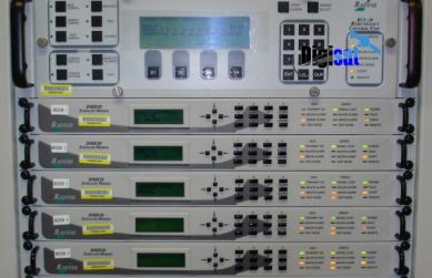
Real-world ground station infrastructure targeting mmWave & sub-THz evolution for satellite communication. Source: Unsplash (CC0).
2. Executive Summary
This article explains why F-Band is gaining traction, where it will first deliver value, and how to specify components that survive 100+ GHz realities. We compare Ka/V/F bands, review use cases, outline metrology practices, discuss manufacturing and materials, and provide a procurement checklist for F-Band 90–140 GHz isolators and F-Band waveguide links. A short market and standardization view rounds out an evidence-based outlook.
3. Ka/V/F-Band Comparison
| Band | Frequency Range | Representative Applications | Strengths | Limitations |
|---|---|---|---|---|
| Ka-Band | 26–40 GHz | Broadband satcom, VSAT, radar altimeters | Mature ecosystem; high capacity | Rain fade; larger antennas vs F-Band |
| V-Band | 50–75 GHz | Wireless backhaul; short-range links | Compact apertures; high throughput | Severe atmospheric attenuation; limited ranges |
| F-Band | 90–140 GHz | Feeder & inter-satellite links; AESA; 6G; imaging | Massive bandwidth; ultra-high resolution | Micron-level tolerances; regulatory immaturity |
Takeaway:
F-Band opens throughput and resolution previously impractical with Ka/V. It is unforgiving on IL/VSWR and manufacturing precision—precisely why isolators and waveguide links matter.
4. Why Isolators & Waveguide Links Matter at F-Band
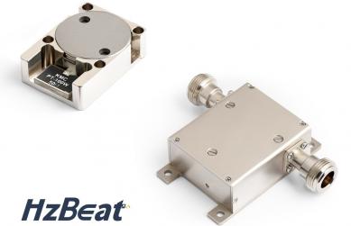
An F-Band 90–140 GHz isolator is a ferrite-based non-reciprocal element that enforces one-way power flow, protecting power amplifiers and sensitive LNAs from reflected energy. At 100+ GHz, even tiny discontinuities inflate return loss; isolators stabilize oscillators, suppress ripple, and maintain measurement sanity. Meanwhile, an F-Band waveguide link offers orders-of-magnitude lower loss and higher power density than coax/microstrip at these frequencies, while providing thermal robustness and mode control. Together they anchor any credible F-Band chain—from antenna feed to TR modules and test ports.
5. Applications: Satellite, Defense Radar, 6G, Imaging
1) Satellite Communication
Constellation operators exploring beyond Ka increasingly consider F-Band for feeder and inter-satellite roles. The promise: multi-Gbps links with compact dishes and improved isolation between uplink/downlink chains. Ground stations adopt F-Band isolators to protect HPAs against mismatch during weather events, while precision F-Band waveguide links preserve EIRP budgets. For gateway design, IL/return-loss budgets at 100+ GHz leave little headroom; proper isolator sizing and waveguide surface finish can swing availability.
2) Defense Radar Systems
Modern AESA radars benefit from F-Band’s tighter beamwidth for discrimination and angle-of-arrival accuracy. Waveguide chains handle high peak power without breakdown; F-Band 90–140 GHz isolators protect MMIC PAs and TR modules during fast T/R switching, reducing ghost targets and extending mean time between failures. Electronic counter-countermeasures also profit from isolator-assisted stability in complex excitations.
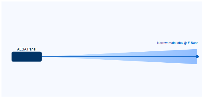
Inline diagram: tighter F-Band beamwidth supports higher angular resolution for defense radar systems.
3) 6G and Beyond Networks
6G research platforms trial F-Band for ultra-short-range access and high-capacity backhaul. Prototype radios pair isolators with frequency extenders and F-Band waveguide links to keep PA/LNA stages stable during beam management and synchronized switching. Multi-band handshakes (e.g., sub-6 GHz control + F-Band data) simplify mobility while isolators suppress oscillation risks in stacked gain stages.
4) Imaging & Scientific Instrumentation
F-Band’s wavelength unlocks resolution regimes for security scanning and advanced MRI coils; precision waveguides enable dielectric spectroscopy and material metrology at sub-THz. Here, isolators reduce standing waves that would otherwise corrupt contrast or S-parameter accuracy.
6. Test & Metrology at 100+ GHz
- Calibration: TRL/LRM with dedicated F-Band standards and waveguide fixtures is essential; even minor flange misalignment impacts phase.
- VNA Extenders: Ensure output power/headroom; put an F-Band 90–140 GHz isolator at the port to reduce ripple and protect multipliers.
- Surface Finish: Loss increases with roughness. Specify split-block waveguides with fine machining and gold plating where feasible.
- Thermal Drift: Stabilize temperature; measure IL/isolation across hot/cold to capture realistic performance.
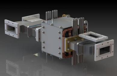
7. Manufacturing, Materials & Packaging
At 100+ GHz, a few microns separate success from failure. Ferrite formulation and bias magnet uniformity set isolation floors; ceramics and plating drive loss. Advanced CNC, micro-EDM, and lithographic micromachining compete on yield. Packaging trends favor split-block waveguide with repeatable flanges; for integration, drop-in elements are explored but face IL/VSWR penalties versus pure waveguide.
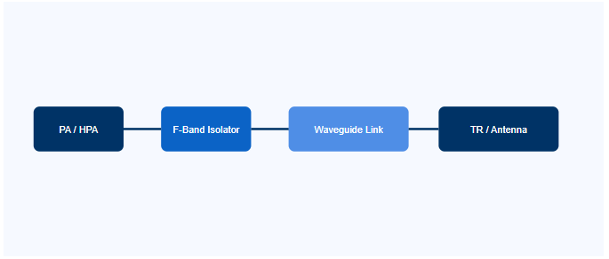
Inline schematic: PA → F-Band 90–140 GHz isolator → F-Band waveguide link → TR/Antenna.
8. Specifying an F-Band Isolator: KPIs & Procurement
When qualifying suppliers, insist on traceable S-parameter data, temperature sweeps, and clearly defined power tests. Below are typical KPIs (illustrative ranges) used by integrators specifying high-frequency RF components for F-Band:
| Metric | Why it matters at F-Band | Typical Targets* | Notes |
|---|---|---|---|
| Insertion Loss (IL) | Throughput/EIRP; small IL erodes link budgets | ≤ 1.2–1.8 dB across sub-band | Depends on bandwidth & package |
| Isolation | Protects PA/LNA; suppresses oscillations | ≥ 18–25 dB (narrow) / 15–20 dB (wide) | Bias uniformity & ferrite quality dominate |
| Return Loss / VSWR | Limits ripple; preserves dynamic range | RL ≥ 14–18 dB (VSWR ≤ 1.5–1.3) | Flange planarity and finish are critical |
| Power Handling | Pulsed radar & high-EIRP satcom | Peak per design; CW 0.5–5 W typical | De-rates with temperature and bandwidth |
| Temperature | Bias point and loss drift vs. °C | −40 to +85 °C (industrial); wider for defense | Test cold/hot S-parameters |
*Illustrative guidance only; final values depend on geometry, materials, biasing, and bandwidth. For custom requirements, contact your supplier.
Supplier checklist:
- Evidence of 100+ GHz builds (micro-tolerance machining, plating, ferrite control).
- Waveguide surface roughness and flange flatness specs in drawings.
- Full S-parameter sets with TRL calibration notes and uncertainty budgets.
- Thermal & vibration screening; burn-in and power cycling data.
- Application notes for F-Band waveguide links and integration with TR modules.
9. Market Outlook & Standardization
Industry analyses project double-digit growth for mmWave components through 2030, with F-Band adoption led by defense and research gateways, then satellite and 6G pilots. On the standards side, global regulators continue exploratory work above 100 GHz; harmonization will unlock scale economics. Early adopters that field reliable F-Band 90–140 GHz isolators and scalable F-Band waveguide links will be first to capture qualified demand.
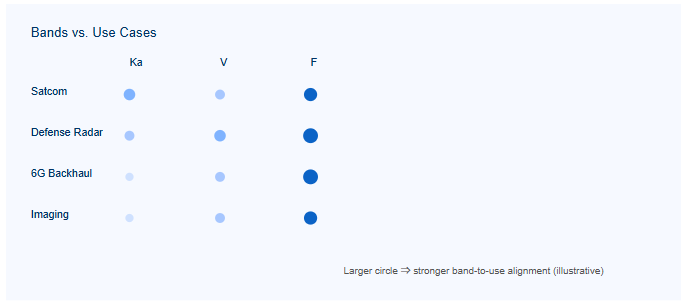
Inline diagram: where F-Band aligns strongest among headline use cases.
10. Challenges & Risk
- Precision risk: sub-10 μm tolerances & flange planarity dominate IL/VSWR.
- Material loss: ferrite and ceramic choices swing dB budgets; plating and finish matter.
- Thermal: self-heating reduces isolation; de-rate CW power accordingly.
- Regulatory: fragmented allocations above 100 GHz delay volume deployment.
- Supply base: small vendor pool; require process capability audits.
11. Future Outlook
We expect early “lighthouse” deployments in defense and research satellites to mature by 2027–2028, with interoperability efforts accelerating thereafter. For 6G, F-Band will likely start as niche backhaul and indoor ultra-bandwidth links before any mass role. As measurement ecosystems stabilize and more suppliers master manufacturing, high-frequency RF components—especially F-Band 90–140 GHz isolators integrated into robust F-Band waveguide links—will form the backbone of next-decade mmWave systems.
12. Conclusion
F-Band is not hype; it is a practical—if demanding—window for capacity and resolution beyond Ka/V. The pairing of F-Band 90–140 GHz isolators and F-Band waveguide links is foundational to stable chains across satellite communication, defense radar systems, and 6G and beyond networks. Teams that invest in metrology, materials, and packaging now will own the learning curve as demand scales.
13. FAQ
Q1: What’s the most common pitfall when moving to F-Band?
A: Underestimating IL and ripple from mechanical tolerances. Add margin; use isolators at critical ports; validate with TRL-calibrated S-parameters.
Q2: Can coax or microstrip replace waveguide at 120 GHz?
A: Generally no for low-loss/high-power chains. Use precision F-Band waveguide links to protect budgets and thermal headroom.
Q3: When should I choose a narrow vs. wide sub-band isolator?
A: Narrow bands yield lower IL/higher isolation; wide bands ease integration but raise IL. Pick per link budget and waveform.
Q4: What supplier data should be “must-have” in RFQs?
A: Full S-parameters (hot/cold), power de-rate curves, flange flatness specs, plating details, and life-test summaries.
14. References
- IEEE Transactions on Microwave Theory and Techniques – Recent advances in sub-THz components and measurement.
- ETSI / ITU exploratory notes on >100 GHz spectrum for 6G and beyond.
- NASA Technical Reports Server – High-frequency satellite communication developments.
- JPL reports on 120 GHz inter-satellite link experiments and path impairments.
- Defense roadmaps discussing AESA evolution at upper mmWave / sub-THz.
- Industry market studies indicating sustained double-digit growth for mmWave components to 2030.
Relateds

About the Author

HzBeat Editorial Content Team
Marketing Director, Chengdu Hertz Electronic Technology Co., Ltd. (Hzbeat)
Keith has over 18 years in the RF components industry, focusing on the intersection of technology, healthcare applications, and global market trends.