2026 Base Station Upgrade Guide: Choosing the Right Isolator to Prevent Signal Interference | HzBeat
Updated on:
Keywords: RF isolator, base station upgrade, 5G interference, 6G communication, high-power isolator, low insertion loss, intermodulation, VSWR, return loss, HzBeat, macro radio, small cell, AAU, backhaul, PIM, MIMO
Summary. As operators densify networks and push toward 6G-readiness in 2026, RF isolators become a decisive safeguard against reflected power, multi-channel intermodulation, and antenna coupling effects. This guide explains how to choose the right isolator—by insertion loss, isolation, power rating, bandwidth, and thermal stability—so your base stations stay linear, compliant, and reliable.
1) 2026 Trends: Why Interference Risk Rises
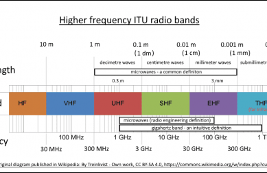
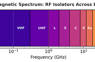
Between late‑5G rollouts and early‑6G trials, 2026 sits at a tricky intersection for radio access networks. Operators are integrating new spectrum layers (from sub‑6 GHz to mmWave), expanding carrier aggregation, and upping massive MIMO densities. Those decisions push the RF front-end toward higher average and peak powers, tighter linearity, and more complex protection schemes. In practice, interference exposure grows in three ways: (1) more transmitters per site, (2) more paths for reflections, and (3) more nonlinear mix products lurking near sensitive receivers.
Whenever a power amplifier (PA) meets a mismatched load, a portion of its output returns as reverse power. If that energy re‑enters the PA, it can stress devices, spike junction temperatures, and trigger gain compression. Worse, the reflected wave can seed intermodulation distortion (IMD) that lands inside in‑band channels. An RF isolator—a non‑reciprocal ferrite component—provides a low‑loss forward path and a high‑loss reverse path, dissipating harmful reflections into an internal load. That’s why isolators are an essential “silent bodyguard” of 2026 upgrade programs.
- Goal:
Lower reverse power - Keep:
Linearity & ACLR - Avoid:
IMD near Rx
2) Where Interference Comes From in Base Stations
2.1 Antenna mutual coupling & site geometry
In dense deployments, cross‑polar arrays, shared masts, and adjacent sectors can couple energy unintentionally. Cabling runs, bends, and connectors add discontinuities that raise VSWR. The reflected energy—if not tamed—becomes a catalyst for mixing and desensitization. Seasonal factors (ice, wind, thermal expansion) and ad‑hoc rooftop co‑tenants modify boundary conditions and change match in subtle but important ways.
2.2 Multicarrier PAs & intermodulation
Consolidated PA shelves that handle multiple carriers increase the chance that IM3/IM5 products fold into operational bands. Transmit combiners and duplexers help, but the simplest “first wall” against reflection‑induced IMD is a correctly specified isolator placed at each PA output or per sector branch. Two‑tone bench tests often show several dB improvement in spur floor after adding isolation.
2.3 Retuned bands, new bands, and old hardware
Refarming and multi‑band aggregation mean legacy components may operate off‑design, widening mismatch. When antennas are retuned or swapped, transient mismatches occur. Isolators cushion those episodes, preserving PA health while crews finalize alignments. During acceptance testing, isolate temperature‑dependent drift and confirm stability with long dwell tests.
3) How to Specify an Isolator that Actually Works
Specmanship can be misleading. Focus on parameters that truly map to field behavior and total cost of ownership:
3.1 Insertion loss (IL)
Target the lowest IL that still meets isolation and power requirements. Every 0.1 dB matters in a linearity‑constrained PA chain. For macro sites, 0.25–0.5 dB IL is common; small cells tolerate slightly higher IL if power budgets allow. Validate IL vs. temperature and mounting torque.
3.2 Isolation
Isolation is the star metric: higher reverse attenuation means less stress on the PA and fewer opportunities for nonlinearities. For macro power classes, ≥ 20–23 dB across band is a practical floor; 25–30 dB offers comfortable margin when antennas see seasonal VSWR swings. Inspect isolation flatness and group delay around band edges.
3.3 Return loss & match
A well‑matched isolator (e.g., RL ≥ 18 dB) avoids becoming a new source of ripple. Evaluate the match over operating temperature; some designs drift at hot/cold corners because of magnetic bias sensitivity. Pay attention to coax connector torque specs and plating quality.
3.4 Power handling (CW & peak)
Check both CW and peak/VSWR‑fault ratings. Ask vendors for data at worst‑case mismatch (e.g., 2:1 or 3:1 VSWR) and for the energy the internal load can dissipate during open/short events. In integrated RRUs, ensure the thermal path under the load is metal‑to‑metal, not through an insulating gasket.
3.5 Bandwidth and flatness
Multi‑band radios require consistent IL/ISO across wide spans. Inspect flatness plots, not just spot numbers. Watch for group delay anomalies near band edges that can harm EVM in wideband OFDM.
3.6 Temperature & magnetic bias stability
Ferrite properties and bias field uniformity dictate drift. For outdoor sites, model −40 °C to +85 °C and solar loading. Shielding & fixture design matter in small enclosures (small cells, RRUs). Include altitude effects if you deploy on high rooftops or mountains.
3.7 Size, mounting, and serviceability
Form factor drives the choice among drop‑in, coaxial, SMT/SMD, or waveguide. Field service favors connectorized units in macros; integrated SMT assemblies shine in compact radios. Verify keep‑out zones for magnetic components near PLLs and LNAs.
3.8 Compliance & reliability artifacts
For operator acceptance, capture HALT/HASS, salt‑fog, vibration, and thermal‑shock evidence. A 2026‑ready isolator should arrive with full S‑parameter sets across temperature and a traceable calibration chain. Request machine‑readable Touchstone files.

4) Application Scenarios & Playbooks
4.1 Macro sector PA chain
Place an isolator right after each PA branch and ahead of any long feeder runs. This protects against connector cycling and ice‑load mismatch. Consider coaxial units with robust heat sinking. For sites with frequent maintenance, quick‑swap mechanics reduce downtime.
- Spec quick start: IL ≤ 0.4 dB, ISO ≥ 25 dB, RL ≥ 18 dB, CW rating ≥ PA avg. + headroom, peak VSWR‑fault proven.
- Field tip: If fans ramp under windy conditions, inspect match: swaying arrays change coupling and detune radomes.
4.2 Massive MIMO / AAU
High element counts amplify coupling paths. Thermal constraints argue for low‑loss drop‑ins near the PA stage on the RF board. Ensure magnetics don’t couple into nearby LNAs or PLLs; perform EMC/EMI scans. Validate isolation uniformity channel‑to‑channel.
4.3 Small cells & neutral‑host venues
For stadiums, airports, and malls, compact radios face varying antenna loads from human bodies and moving signage. SMT/SMD isolators offer tight integration; prioritize flat IL and solid ISO over temperature. Protect against humidity using conformal coatings where appropriate.
4.4 Microwave backhaul
Backhaul radios (6–42 GHz) often use waveguide or mini‑coax front‑ends. Waveguide isolators excel at high power and low IL. Guard against moisture ingress; verify gasket and plating integrity after thermal cycling. Consider pressure‑sealed enclosures in coastal zones.
5) Validation, Burn‑In, and Field Reliability
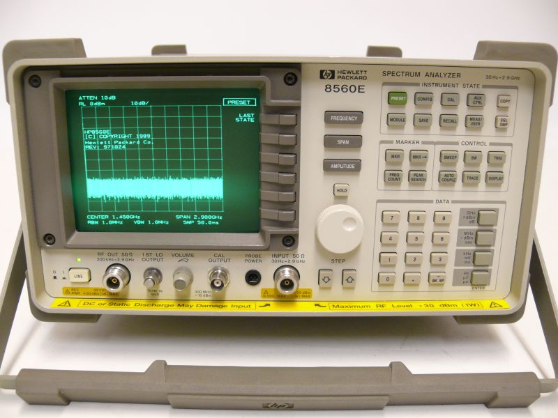
5.1 S‑parameter and large‑signal evaluation
Beyond VNA sweeps, run two‑tone tests to quantify IL vs. power and the isolator’s contribution to IMD. Measure reverse isolation under modulated waveforms at elevated case temperatures. Capture baseline vs. post‑change data for traceability.
5.2 VSWR fault and mismatch survivability
Simulate open/short and 3:1 VSWR while monitoring load temperature. A well‑designed isolator limits reverse power into the PA and safely shunts energy to its load without runaway. Add a thermal sticker or sensor on the load for commissioning visibility.
5.3 Thermal path and enclosure design
Derate based on real enclosure θJA and solar load. Use conductive paths and avoid insulating gaskets under the load pad. Consider heat spreaders in fanless RRUs and verify no hot spots using IR camera scans during power soak.
5.4 Environmental & lifetime
Prove resistance to humidity, salt spray (coastal towers), and vibration. Track mean time between failure and include isolators in RMA screening to spot connector‑related infant mortality. Ensure proper strain relief on jumpers to prevent micro‑movement PIM.
6) Lightweight Solutions & Customization (by HzBeat)
For 2026 upgrades, a lightweight brand mention is enough: HzBeat supplies drop‑in, coaxial, SMT/SMD, and waveguide isolators spanning sub‑6 GHz to tens of GHz, with engineering support for low insertion loss, wideband isolation, and PA fault energy handling. OEM/ODM customization is available—band targeting, thermal layout, magnetic bias tuning, and reliability evidence. Contact: [email protected].
Conclusion
Interference risks climb as sites densify and spectrum widens in 2026. The right RF isolator—chosen by verifiable IL/ISO, match, power robustness, bandwidth, and stability—keeps transmitters linear, protects PAs against reflections, and preserves receiver sensitivity. Design in the isolator early, validate under mismatch and temperature corners, and you will ship upgrades that stay quiet in the field.
FAQ
Q1. What happens if I don’t use an isolator in a base station PA chain?
Expect higher reverse power into the PA, more frequent gain compression under mismatch, elevated junction temperatures, and increased IMD that can desensitize nearby receivers.
Q2. Coaxial vs. drop‑in vs. SMT—how do I choose?
Macros favor connectorized coaxial for serviceability. AAUs and small cells use drop‑ins/SMT for integration and thermal control. Waveguide is preferred for high‑power microwave backhaul.
Q3. What insertion loss is acceptable?
For macro PAs, 0.25–0.5 dB is a practical range; lower is better if isolation and power constraints are still met.
Q4. How do I verify isolation margin across temperature?
Request S‑parameters at cold/room/hot, then re‑measure in a thermal chamber with the device mounted in the intended enclosure to capture bias drift and mounting effects.
Relateds

About the Author

HzBeat Editorial Content Team
Sara is a Brand Specialist at Hzbeat, focusing on RF & microwave industry communications. She transforms complex technologies into accessible insights, helping global readers understand the value of circulators, isolators, and other key components.