What Is the Purpose of an RF Circulator?
Updated on:
Keywords: RF circulator, 3-port circulator, non-reciprocal device, ferrite circulator, waveguide circulator, microstrip circulator, drop-in circulator
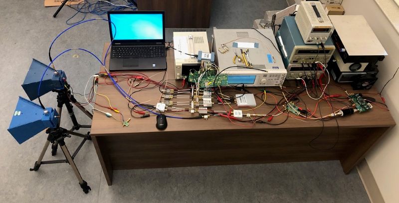
Hero image: microwave lab environment for RF component measurement.
1. Introduction: Why Circulators Exist
Real RF systems are full of reflections, switching, and bidirectional flows. A transmitter wants to push energy toward the antenna; a receiver wants to listen to faint echoes; a test port wants the device-under-test to see a tame environment. The RF circulator solves these routing and isolation problems in one elegant passive component. A classic three-port circulator routes energy from Port 1 → Port 2, Port 2 → Port 3, and Port 3 → Port 1, while strongly attenuating the reverse paths. In other words, it’s a directional traffic circle for microwaves.
Circulators are indispensable in radar T/R modules, full-duplex radios, test fixtures, and antenna sharing networks where transmit and receive chains must coexist without corrupting each other. They provide the clean pathway that active devices need—without the noise, oscillation risk, or measurement drift that reflections would otherwise inject.
2. Working Principle & S-Parameters
RF circulators are non-reciprocal ferrite devices biased by a static magnetic field. The bias forces gyromagnetic precession in the ferrite, breaking time-reversal symmetry. In a junction geometry (Y-junction is common), modal rotation steers energy from one port to the next in a fixed order. The result is a unidirectional transfer around the three ports, with reverse paths presented to an internal or external resistive load.
S-parameter view. Label the ports 1,2,3 in the circulation order. An ideal device has |S21|≈0 dB, |S32|≈0 dB, |S13|≈0 dB (forward directions), and very low reverse terms |S12|, |S23|, |S31|. Practical circulators aim for low insertion loss in forward paths and high isolation in reverse paths across the specified bandwidth and temperature range.
Design note: Magnetic bias, ferrite properties, and junction geometry co-determine bandwidth and loss. At higher bands (X/Ku/Ka/W), waveguide geometries often yield lower loss and higher power headroom than planar versions.
3. The Practical Purpose of an RF Circulator
In one sentence: a circulator routes energy predictably while protecting active devices from troublesome reverse power. That simple idea unlocks key system capabilities:
- Transmit/Receive coexistence: Route TX power to the antenna while routing antenna echoes to the RX—without a bulky relay or lossy switch network.
- Full-duplex & self-interference mitigation: A circulator provides the first line of isolation between simultaneous TX and RX chains, easing SIC algorithms and linearization.
- Source/load decoupling: The source sees a tame environment despite antenna or DUT mismatch dynamics; the load is shielded from source variability.
- Measurement stability: Bench setups achieve repeatable readings by steering reflections into a termination instead of back into instruments.
4. System-Level Benefits & Design Impact
While a circulator adds a fraction of a dB in loss, it often reduces overall system loss once the knock-on benefits are counted: lower rework, less guardbanding, higher PA efficiency (thanks to calmer VSWR), and fewer BOM items compared to active switch networks for certain topologies. In multi-carrier systems, it helps suppress PIM mechanisms tied to fluctuating boundary conditions. In high-power chains, it limits stress on expensive GaN stages by steering reflected energy away from the die.
From an architecture perspective, circulators enable compact T/R modules, simplify duplexing, and offer graceful degradation: if the antenna detunes in the field, the transmitter doesn’t immediately suffer catastrophic oscillations or fold-back events.
5. Where Circulators Shine (Industry Examples)
- Radar (X/Ku/Ka/W-band): The TX pulse flows PA → circulator → antenna; returns flow antenna → circulator → LNA. Waveguide circulators excel for peak/average power and low IL.
- 5G/6G Radio Units & Small Cells: Circulators at the PA output provide isolation to the antenna port and help keep EVM/ACLR in spec as user proximity or weather shifts impedance.
- Satcom Terminals & Gateways: Feed networks use circulators to separate uplink and downlink paths cleanly with minimal added noise figure.
- Medical Imaging (MRI/NMR): T/R switching with circulators prevents the strong TX pulse from desensitizing or damaging the receive chain.
- Measurement Benches: Test ports insert circulators to absorb DUT reflections and improve calibration stability across fixtures and operators.
- Quantum & Cryogenic Labs: Low-loss circulators (and their cryo-optimized cousins) enforce directionality in ultra-low-noise microwave lines.
6. Types of RF Circulators & Selection Scenarios
Circulator format depends on frequency, power, environment, and integration style. HzBeat supplies all major families to simplify the trade-offs:
- Microstrip Circulators — PCB-mount, ultra-compact; great when SWaP dominates and power is moderate. Common in small radios and integrated modules.
- Drop-In Circulators — cavity-mounted with screws; favored in aerospace/defense where mechanical control and screening are tight; excellent for broadband variants.
- Coaxial Circulators — connectorized (SMA/N/2.92 mm); robust for instrumentation, cabinets, and field retrofits; typically broadband and serviceable.
- Waveguide Circulators — best for high frequencies and high peak/average power with the lowest insertion loss; ideal for radar and SATCOM feeds.
Heuristic: Below C-band at modest power → microstrip / coaxial; at X-band and above or at high peak/average power → waveguide. For module-level aerospace designs, drop-in is a reliable middle ground.
7. Key Specifications: What to Look For
When comparing datasheets, focus on these headline parameters, then refine for environment and reliability:
- Frequency & Bandwidth: Center frequency, useful fractional bandwidth, and the flatness of IL/Isolation over temperature.
- Insertion Loss (forward paths): 0.2–0.6 dB is common; every tenth of a dB matters for PA efficiency and RX NF.
- Isolation (reverse paths): 18–30 dB typical; precision or narrowband versions exceed 30 dB.
- Return Loss / VSWR: ≤1.25:1 (≈20–23 dB RL) at each port is a good target for high-quality devices.
- Power Handling: Specify CW, peak, and mismatch (e.g., 3:1 VSWR) at max ambient; confirm the termination’s thermal path.
- Temperature Stability: Performance drift of IL/Isolation vs. temperature and bias; typical −40 °C…+85 C operation.
- Size/Weight/Connectors: Critical in airborne, space, and handheld platforms.
- Reliability & Screening: Burn-in, thermal cycling, vibration; for space, radiation data and lot screening.
8. Integration Tips: Placement, Matching, Heat
Placement. In T/R chains, place the circulator directly at the PA output and LNA input node to minimize additional discontinuities. Keep interconnects short and well-controlled.
Impedance control. Follow land patterns, via fences, and cavity drawings for microstrip/drop-in units; use high-quality connectors with proper torque for coaxial types; avoid tight bends near ports.
Thermal path. Reverse energy ends up in a load. Provide a low thermal resistance path (heatsink, chassis contact, TIM). For high-duty radar or multi-carrier radios, simulate worst-case mismatch and confirm junction temps.
Magnetic environment. Keep external magnets or ferromagnetic materials away from the device; respect keep-out zones to preserve internal bias uniformity.
9. Circulator vs. Isolator: When to Terminate
A circulator becomes an isolator when one port is terminated with a matched load. This is powerful in practice:
- As an isolator: Terminate Port 3; forward path 1→2 is low loss; reverse reflections 2→3 are absorbed in the load, protecting the source at Port 1.
- As a duplexer helper: Use all three ports: TX → Port 1, Antenna → Port 2, RX → Port 3. Reflections are steered away from sensitive devices.
If your goal is pure one-way protection, consider a dedicated isolator; if you need routing plus protection, keep it as a circulator and exploit all three ports.
10. HzBeat Circulator Portfolio (20 MHz–200 GHz)
HzBeat delivers circulators across all mainstream formats, balancing insertion loss, isolation, bandwidth, and power handling for telecom, aerospace, SATCOM, medical, and research markets:
- Microstrip Circulator — PCB-mount miniaturization, ideal for compact radios.
- Drop-In Circulator — aerospace-grade mechanical stability and broadband options.
- Coaxial Circulator — rugged connectorized designs for instrumentation and field deployments.
- Waveguide Circulator — low loss and high power headroom for X/Ku/Ka/W-band front-ends.
Need a specific band, connector, or environmental screening? Email [email protected] for OEM/ODM support.
11. Future Directions: mmWave, THz & Miniaturization
Three clear vectors shape circulator roadmaps: miniaturization (LTCC and thin-film ferrites shrink form factors and enable SiP/MMIC integration), broadbanding (multi-section junctions and advanced magnetics widen useful bandwidth), and power density (improved thermal paths and low-loss dielectrics push average power higher without penalizing IL). At the frontier, cryogenic and quantum systems require ultralow-loss, low-magnetic-noise devices that preserve directionality at millikelvin temperatures.
12. Executive Summary
An RF circulator is a three-port, non-reciprocal traffic circle for microwaves: it routes TX energy where it must go, sends echoes where they should be measured, and keeps reflections out of harm’s way. The small cost in insertion loss typically returns with dividends in stability, measurement repeatability, and architecture simplicity. Choose the right format for your band and power, match it well, give the termination a cool home, and your system will repay you with cleaner performance and higher uptime.
FAQ
What’s the difference between an RF circulator and an RF isolator?
A circulator has three ports and routes energy 1→2, 2→3, 3→1. Terminating one port converts it into a two-port isolator that passes forward power and absorbs reverse power.
How much isolation do I need?
Many radios target ≥20 dB across the band; precision measurement or sensitive oscillators may call for 25–30 dB. Validate across temperature and anticipated VSWR.
Which format should I pick?
Microstrip/coaxial for compact, moderate-power designs below C-band; waveguide for high frequency and high peak/average power; drop-in when you need cavity control and screening.
Will a circulator improve EVM/ACLR?
Indirectly, yes—by stabilizing the PA’s load and reducing reverse-wave-induced distortion, which often improves modulation metrics and simplifies DPD.
Relateds


About the Author

HzBeat Editorial Content Team
Marketing Director, Chengdu Hertz Electronic Technology Co., Ltd. (Hzbeat)
Keith has over 18 years in the RF components industry, focusing on the intersection of technology, healthcare applications, and global market trends.