How to Choose the Right RF Isolator for High-Reliability Microwave Systems
Updated on:
Keywords: RF circulator, isolator, microwave isolator selection, high-reliability RF components, insertion loss vs. isolation, ferrite devices, drop-in isolator, coaxial isolator, power handling, IMD, VSWR
In high-reliability microwave systems—spanning satellite payloads, radar transmitters, and critical medical infrastructure—the RF isolator is often the unsung hero. It serves as the primary defense mechanism for sensitive sources, such as power amplifiers (PAs) and oscillators, protecting them from excessive reflected power caused by load mismatches. Selecting the correct isolator is not merely about matching frequency bands; it requires a rigorous analysis of insertion loss, thermal dissipation, intermodulation distortion (IMD), and package reliability.
Core Electrical Specifications: The "Big Three"
The foundation of selecting an isolator lies in balancing the three primary electrical parameters: Isolation, Insertion Loss, and VSWR. In high-reliability engineering, these are often mutually dependent trade-offs rather than independent variables.
- Isolation (dB): This defines the device's ability to attenuate reverse power. For a single-junction ferrite isolator, typical isolation ranges from 20 dB to 25 dB. In critical systems where even minimal reflection can destabilize a GaN or GaAs amplifier, cascading junctions (dual-junction isolators) may be necessary to achieve >50 dB isolation, albeit at the cost of size and insertion loss.
- Insertion Loss (IL): Every decibel lost in the forward path equates to wasted power and increased heat. In high-power applications, an IL difference between 0.3 dB and 0.5 dB can result in significant thermal stress. High-quality ferrite materials and optimized magnetic biasing are required to minimize IL.
- VSWR (Voltage Standing Wave Ratio): The input and output ports must be matched to the system impedance (usually 50Ω). A high-reliability isolator typically demands a VSWR better than 1.20:1 to ensure seamless integration without creating secondary reflection points.
Tips:
Always specify isolation bandwidth rather than just center frequency. Narrowband isolators generally offer superior performance (higher isolation, lower loss) compared to octave-band devices.
Power Handling and Thermal Management
Failure in RF isolators is rarely subtle; it is often catastrophic, involving thermal runaway or ferrite cracking. Understanding the distinction between Forward Power and Reverse Power handling is vital.
Forward power handling is limited by the device's insertion loss and the ability of the housing to dissipate generated heat. However, Reverse Power handling is the more critical metric for isolators, as the internal termination load must absorb the full reflected energy in the event of a downstream open or short circuit.
| Parameter | Description | High-Rel Requirement |
|---|---|---|
| CW Power | Continuous Wave power capability | Must account for temperature derating (usually starts >70°C). |
| Peak Power | Short duration pulse handling | Crucial for radar; breakdown voltage of the dielectric is the limit. |
| Termination Rating | Power the internal load can absorb | Should be rated for 100% of the PA output power for full protection. |
In high-altitude or space applications, the Multipactor effect (breakdown under vacuum) must also be considered for high-power units, requiring specialized venting or potting.
Package Styles: Drop-in vs. Coaxial vs. Surface Mount
The mechanical interface dictates how the isolator integrates into the wider system architecture. Choosing the wrong package can introduce unwanted parasitic inductance or thermal bottlenecks.
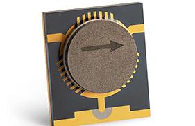
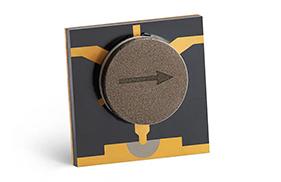
- Drop-In Isolators: These are integrated directly into stripline or microstrip circuits. They offer a compact footprint and eliminate connectors, reducing insertion loss. However, they require precise grounding and heat sinking to the host PCB or chassis.
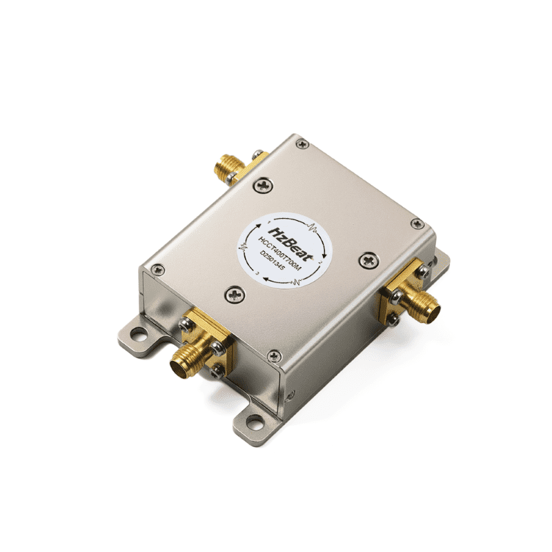
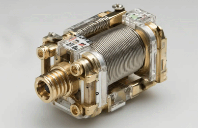
- Coaxial Isolators: Equipped with connectors (SMA, N-Type, 2.92mm), these are robust, "plug-and-play" solutions ideal for rack-mounted systems or testing environments. They provide excellent mechanical shielding but are bulkier.
- Surface Mount (SMT): Used in high-volume, lower-power commercial applications. For high-reliability sectors, SMT isolators must be carefully evaluated for solder joint fatigue under thermal cycling.
Intermodulation Distortion (IMD) and Linearity
For modern communication systems using complex modulation schemes (like QAM or OFDM), Intermodulation Distortion (IMD) is a critical specification. Ferrite materials are inherently non-linear. When two or more signals mix within the ferrite, they create spurious products (typically 3rd order, 2f1-f2) that can interfere with adjacent channels.
High-reliability isolators minimize IMD by selecting ferrite materials with specific saturation magnetization properties and ensuring tight assembly tolerances. In specifications, look for the 3rd Order Intercept Point (IP3) or a specific IMD rating (e.g., -70 dBc) to ensure the device will not degrade the Signal-to-Noise Ratio (SNR) of the system.
Tips:
Placement matters: Isolators are magnetic. Avoid placing them near steel screws, fan motors, or other ferromagnetic materials, as this can detune the magnetic bias field and degrade performance.
Summary
Selecting the right RF isolator for high-reliability systems is a multi-dimensional optimization problem. It requires looking beyond simple frequency ranges to analyze the thermal path, the robustness of the internal termination, and the linearity of the ferrite material. For critical missions, engineers should prioritize derating power capabilities by at least 50% and ensuring the isolation bandwidth provides sufficient margin for temperature drift.
By rigorously defining requirements for Isolation, VSWR, Package Type, and Environmental conditions, you ensure that the isolator serves its purpose: acting as an invisible shield that prolongs the life of active microwave components.
FAQ: RF Isolator Selection
Relateds

About the Author

HzBeat Editorial Content Team
Sara is a Brand Specialist at Hzbeat, focusing on RF & microwave industry communications. She transforms complex technologies into accessible insights, helping global readers understand the value of circulators, isolators, and other key components.