RF Circulator Meets Antenna: Reducing Signal Reflections for Reliable Communication Links
Updated on:
Keywords: RF Circulator, Antenna Isolation, Signal Reflections, VSWR (Voltage Standing Wave Ratio), Return Loss, Reliable RF Communication Links
A practical engineering guide to using nonreciprocal RF circulators for antenna isolation, lower VSWR, and stable PA operation across radar, satellite, and 5G front-ends.
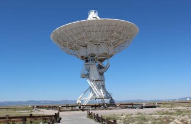
Between every transmitter and every antenna lies an invisible challenge: signal reflections. This article shows how an RF circulator for antenna isolation helps reduce signal reflections in RF systems, protect power amplifiers, and deliver reliable RF communication links.
I. The Science of Reflections — Why They Matter
At the antenna interface, any impedance mismatch creates a reflected wave that travels back toward the transmitter. The magnitude of that wave is commonly expressed as Return Loss (S11) and VSWR. A high return loss (e.g., > 20 dB) and a low VSWR (e.g., 1.2:1) indicate good matching. Poor matching raises junction temperatures, reduces link margin, and can trigger PA foldback or oscillation.
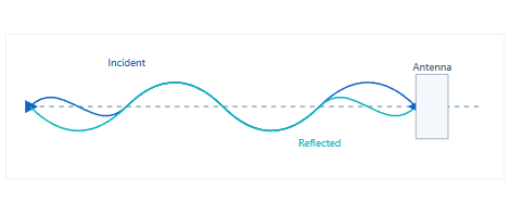
Fig. 1 — Incident and reflected waves at the antenna port.
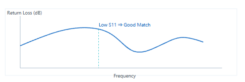
Fig. 2 — Example return loss (S11) curve.
Long-tail takeaway:
Improving antenna matching and reducing signal reflections in RF systems directly increases link margin and PA lifetime.
II. The RF Circulator — Nonreciprocity at Work
An RF circulator is a three-port nonreciprocal device that enforces a preferred direction of power flow: Port 1 → 2, 2 → 3, 3 → 1. In a transmitter chain, the PA output drives Port 1; the antenna is connected at Port 2; and a 50-ohm load is attached at Port 3. Reflected energy from the antenna is steered into Port 3 rather than back to the PA, improving antenna isolation and link stability.
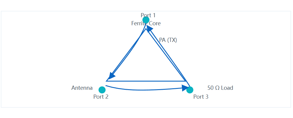
Fig. 3 — Three-port circulator used for antenna isolation.
Key performance metrics include Insertion Loss (IL), Isolation (ISO), Return Loss (S11), VSWR, and Power Handling. For many communication links, practical targets are IL < 0.5 dB and ISO> 20–23 dB across temperature. Lower IL translates directly into higher effective radiated power; higher ISO means better PA protection and cleaner receiver desense performance.
| Parameter | Typical Target | Engineering Note |
|---|---|---|
| Insertion Loss (IL) | < 0.5 dB | Lower IL yields higher TX efficiency and link margin. |
| Isolation (ISO) | > 20–23 dB | Higher ISO shunts reflections away from the PA. |
| Return Loss (S11) | > 18–20 dB | Improves matching and reduces standing waves. |
| VSWR | ≤ 1.25:1 | Complementary to S11; lower values indicate better match. |
| Power Handling | Band/application-dependent | Consider duty cycle, crest factor, and thermal path. |
III. Circulator–Antenna Co-Design: From S-Parameters to Reliability
Effective reflection control is a system problem. Alongside the RF circulator for antenna isolation, engineers must optimize the antenna feed, transmission line width, and the mechanical stack-up. Co-design improves link reliability and avoids late-stage surprises in the chamber.
Packaging & Integration
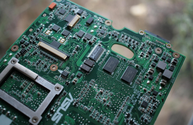
- Microstrip Circulator — compact PCB integration for low-to-mid power modules. Explore microstrip options.
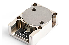
- Drop-in Circulator — balance of thermal path and footprint for RF front-ends. See drop-in families.
- Coaxial Circulator — connectorized modules for robust field deployment. Coaxial portfolio.
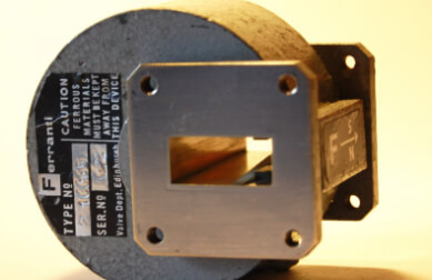
- Waveguide Circulator — low loss for high-power microwave/mmWave links. Waveguide line-up.
Band Targets & Use Cases (long-tail ready)
| Band | Example Use | Long-Tail Angle |
|---|---|---|
| L/S/C | Telemetry, ground stations | “how to reduce signal reflections in RF systems” |
| X/Ku | Phased-array radar, satellite uplink | “high-isolation circulator for satellite uplink” |
| Ka/V/W | Backhaul, satcom user terminals | “Ka-band circulator for antenna isolation” |
| D/F (110–170+ GHz) | mmWave R&D testbeds | “waveguide circulator for high-power antenna systems” |
Tip:
Pair the circulator with a precision 50-Ω load (Port 3) rated for your crest factor and thermal budget. This ensures reflected power is safely dissipated.
IV. Real-World Performance — Lab to Link
Quantifying the benefit of a circulator typically involves measuring S11 and TX output stability with and without the device inline. In array transmit tiles, engineers also track receiver desense and in-band intermodulation products under high VSWR conditions.
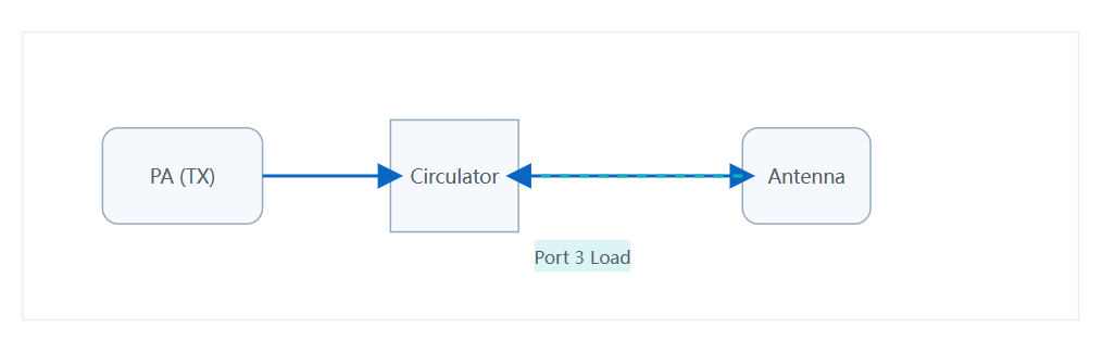
Fig. 4 — Reflection control in practice.
In field deployments, engineers report improvements such as return loss increases of 3–5 dB at the PA plane and markedly lower PA foldback events under mismatch. For high-peak-ratio waveforms (e.g., OFDM), consider the load’s thermal resistance and time-average power rating.
V. HzBeat Approach — Engineering Clarity
HzBeat supports custom circulator solutions spanning PCB-level microstrip to high-power waveguide modules. Our design philosophy is to minimize insertion loss, maximize isolation, and guarantee thermal robustness across your duty cycle. Whether you are building 5G base stations, phased-array radar, or satellite uplink systems, we can tune the circulator to your link budget and environmental profile.
- Wide band coverage from VHF/UHF through microwave and mmWave.
- Low IL designs for tighter power budgets and higher EIRP.
- ISO-first topologies to protect PAs and reduce receiver desense.
- Packaging options: Microstrip, Drop-in, Coaxial, Waveguide.
- Qualification and test support (S-parameters, power/thermal, environmental).
VI. FAQ
1) What causes reflection in antenna systems?
Impedance mismatch across connectors, transmission line transitions, and antenna feed geometry. Mechanical tolerances, temperature drift, and moisture can move resonance away from design frequency.
2) How does a circulator improve link reliability?
By shunting reflected power into a matched load, the PA sees a more benign load line over frequency and temperature. This stabilizes output power and reduces distortion under mismatch.
3) What’s the difference between a circulator and an isolator?
A circulator is a three-port device with directional flow; an isolator is typically a two-port subcase of a circulator with Port 3 internally terminated. Isolators simplify integration when you only need one direction of propagation.
4) How do I validate the improvement?
Measure S11 at the PA output with and without the circulator; run power sweeps into controlled VSWR fixtures; check EVM/ACLR on your modulation; and validate thermal margins on the Port-3 load.
VII. References
- [1] David M. Pozar, Microwave Engineering, 4th ed., Wiley, 2012.
- [2] Robert E. Collin, Foundations for Microwave Engineering, 2nd ed., IEEE Press/Wiley, 2001.
- [3] IEEE Std 149-2021, IEEE Standard for Antenna Measurements, 2021.
- [4] Ludwig, R., Bretchko, P., RF Circuit Design: Theory and Applications, 2nd ed., Prentice Hall, 2000.
- [5] Keysight Technologies, Network Analysis Basics (App Note), various editions.
- [6] IEEE Std 1785-2a-2018, Rectangular Waveguides and Components – Waveguide Interfaces, 2018.
- [7] Rohde & Schwarz, Measuring S‑parameters with a Vector Network Analyzer (Application Note), various editions.
- [8] Microwaves101, “Circulators and Isolators” (Industry Reference), continuously updated.
VIII. Conclusion
The combination of a well-matched antenna and a nonreciprocal RF circulator is a proven way to reduce signal reflections and preserve amplifier health. With careful packaging selection and Port-3 load design, you gain margin where it matters most: a reliable communication link.
Need help choosing the right model? Contact us with your band, power, IL/ISO targets, and footprint constraints—we’ll propose a tuned solution.
Relateds


About the Author

HzBeat Editorial Content Team
Marketing Director, Chengdu Hertz Electronic Technology Co., Ltd. (Hzbeat)
Keith has over 18 years in the RF components industry, focusing on the intersection of technology, healthcare applications, and global market trends.